

![499 3 x L Lx L=259 mm 1 2. K L Case # 1 - upward Force at [F] of 191N ↑ Forces in members: 1=226N, 2 = 171N, 3= ON, U=ON, 5=U](http://img.homeworklib.com/questions/be817150-d496-11ea-8bab-dbe64d46a5df.png?x-oss-process=image/resize,w_560)

Homework Answers


Add Answer to:
Weyheit & Figure 2: Loading Case 1 ORT Figure 3: Loading Case 2 499 3 x...
A roof truss is loaded and supported as shown in Figure 2. The joints are all...
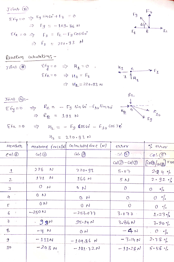
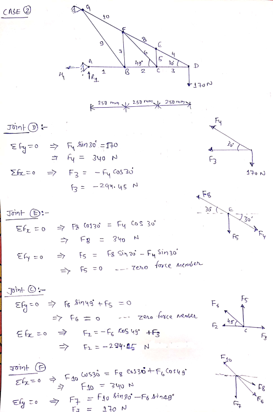
 A roof truss is loaded and supported as shown in Figure 2. The joints are all pinned. (a) Determine the support reactions at A and G. (25 marks) (b)Using "Method of joints" find the forces in members AB, AF, GF, CD and DE of the truss. State whether each of these members is in tension or compression. (75 marks) (c) Determine the force in members BC, CF and EF of the truss using "Method of sections". State whether each of...
Write the MATLAB code and use the function linsolve() to solve the system of linear equations. Thank you! l Truss A truss is a structure that typically consists of 1. All straight members 2. connected...
 Write the MATLAB code and use the function linsolve() to solve
the system of linear equations.
Thank you!
l Truss A truss is a structure that typically consists of 1. All straight members 2. connected together with pin joints 3. connected only at the ends of the members 4. and all external forces (loads&reactions) must be applied only at the joints. The weights of the members may be neglected. The basic building block of a truss is a triangle. Large...
Write the MATLAB code and use the function linsolve() to solve
the system of linear equations.
Thank you!
l Truss A truss is a structure that typically consists of 1. All straight members 2. connected together with pin joints 3. connected only at the ends of the members 4. and all external forces (loads&reactions) must be applied only at the joints. The weights of the members may be neglected. The basic building block of a truss is a triangle. Large...
Homework Problem H 7.E Consider the truss shown below with the loading on joints D, K, S and U. Given: Find: For this p...
 Homework Problem H 7.E Consider the truss shown below with the loading on joints D, K, S and U. Given: Find: For this problem: a) Determine the external reactions acting on the truss at supports A and H b) Identify all zero-force members in the truss. c) Determine the load carried by members BC, CJ and MN. Identify each member as either being in tension, in compression or carrying zero load. For this problem, use the following parameters: h 30...
1. Determine the forces in members DF and FE of the double-pitch roof truss shown. State...
 1. Determine the forces in members DF and FE of the double-pitch
roof truss shown. State whether each of those members is in tension
or compression.
2. For the given loading, determine the zero-force members in
each of the truss shown.
1. Determine the forces in members DF and FE of the double-pitch roof truss shown. State whether each of those members is in tension or compression. - 4m 4m 4m 3m 3m KV 6 m 0.75 kN 6m 6...
1. Determine the forces in members DF and FE of the double-pitch
roof truss shown. State whether each of those members is in tension
or compression.
2. For the given loading, determine the zero-force members in
each of the truss shown.
1. Determine the forces in members DF and FE of the double-pitch roof truss shown. State whether each of those members is in tension or compression. - 4m 4m 4m 3m 3m KV 6 m 0.75 kN 6m 6...
Question Four: For the pin-jointed truss shown in Figure 4, 3m 12 KN 3m 30 kN 3m 15 kN 4m 4m 3m 3m 6m Figure 4. Calcula...
 Question Four: For the pin-jointed truss shown in Figure 4, 3m 12 KN 3m 30 kN 3m 15 kN 4m 4m 3m 3m 6m Figure 4. Calculate the reactions at A and B. (a) By inspection (involving no calculations), list all the zero force members. (b) (c) By method of joints, analyse joints T, S and N to determine the force in members ST NT, RS, SN, MN and RN. In your answer, you must state whether the members are...
Given: The Truss and loading shown in the diagram below Find: The reactions and forces in...
 Given: The Truss and loading shown in the diagram below Find: The reactions and forces in the members. Draw a Free Body Diagram clearly showing the reactions. List the member forces in the table including indicating if they are Tension or Compression. 500 lb Reactions Force Ay BX 4ft Member Force ft 3 ft 3ft
Problem 2 For the truss shown in the figure, a) Identify the zero-force members. b) Determine...
 Problem 2 For the truss shown in the figure, a) Identify the zero-force members. b) Determine the forces in members ij & ih by the k 200N 100N Method of Joints c) Determine the force in member df by the Method of Sections. (Specify whether Tension or Compression). 3 m 3m
A 8 c 2 Based on the loading and geometry above (assume vertical members are perpendicular...
 A 8 c 2 Based on the loading and geometry above (assume vertical members are perpendicular to chords and chords are parallel) Is the force in member GH tension, compression, zero, or indeterminate? Tension O Compression Zero Indeterminate QUESTION 10 Where Is it ok to load a truss? O anywhere O along chords on the webs At nodes QUESTION 11 A c ܐܠܬ m Based on the loading and geometry above (assume vertical members are perpendicular to chords and chords...
Problem No. 2 (100 points) For the Baltimore bridge truss shown below answer the following questions:...
 Problem No. 2 (100 points) For the Baltimore bridge truss shown below answer the following questions: 1) Calculate Reaction Forces (FBD is already drawn assuming a pin support at A and a roller support at I) (10) 2) What is status of the Truss (determinate or indeterminate)? (10) 3) Obtain ALL the Zero force member (30) 4) Using method of Joints, find force in member PF and PG specify if these forces are in Tension or Compression? (25) 5) Using...
Engineering Statics Quiz 6 (Take Home Quiz 3) 800 N Based on the truss above, determine:...
 Engineering Statics Quiz 6 (Take Home Quiz 3) 800 N Based on the truss above, determine: a. Which members do you think are zero force members? Write a short explanation of why for each. b. The reactions of the pin support at A and the rolling support at C. C. The load in each member, as well as whether it is in tension or compression, using the method of joints d. Draw a TC Diagram for your solution.
 A roof truss is loaded and supported as shown in Figure 2. The joints are all pinned. (a) Determine the support reactions at A and G. (25 marks) (b)Using "Method of joints" find the forces in members AB, AF, GF, CD and DE of the truss. State whether each of these members is in tension or compression. (75 marks) (c) Determine the force in members BC, CF and EF of the truss using "Method of sections". State whether each of...
 Write the MATLAB code and use the function linsolve() to solve
the system of linear equations.
Thank you!
l Truss A truss is a structure that typically consists of 1. All straight members 2. connected together with pin joints 3. connected only at the ends of the members 4. and all external forces (loads&reactions) must be applied only at the joints. The weights of the members may be neglected. The basic building block of a truss is a triangle. Large...
Write the MATLAB code and use the function linsolve() to solve
the system of linear equations.
Thank you!
l Truss A truss is a structure that typically consists of 1. All straight members 2. connected together with pin joints 3. connected only at the ends of the members 4. and all external forces (loads&reactions) must be applied only at the joints. The weights of the members may be neglected. The basic building block of a truss is a triangle. Large...
 Homework Problem H 7.E Consider the truss shown below with the loading on joints D, K, S and U. Given: Find: For this problem: a) Determine the external reactions acting on the truss at supports A and H b) Identify all zero-force members in the truss. c) Determine the load carried by members BC, CJ and MN. Identify each member as either being in tension, in compression or carrying zero load. For this problem, use the following parameters: h 30...
 1. Determine the forces in members DF and FE of the double-pitch
roof truss shown. State whether each of those members is in tension
or compression.
2. For the given loading, determine the zero-force members in
each of the truss shown.
1. Determine the forces in members DF and FE of the double-pitch roof truss shown. State whether each of those members is in tension or compression. - 4m 4m 4m 3m 3m KV 6 m 0.75 kN 6m 6...
1. Determine the forces in members DF and FE of the double-pitch
roof truss shown. State whether each of those members is in tension
or compression.
2. For the given loading, determine the zero-force members in
each of the truss shown.
1. Determine the forces in members DF and FE of the double-pitch roof truss shown. State whether each of those members is in tension or compression. - 4m 4m 4m 3m 3m KV 6 m 0.75 kN 6m 6...
 Question Four: For the pin-jointed truss shown in Figure 4, 3m 12 KN 3m 30 kN 3m 15 kN 4m 4m 3m 3m 6m Figure 4. Calculate the reactions at A and B. (a) By inspection (involving no calculations), list all the zero force members. (b) (c) By method of joints, analyse joints T, S and N to determine the force in members ST NT, RS, SN, MN and RN. In your answer, you must state whether the members are...
 Given: The Truss and loading shown in the diagram below Find: The reactions and forces in the members. Draw a Free Body Diagram clearly showing the reactions. List the member forces in the table including indicating if they are Tension or Compression. 500 lb Reactions Force Ay BX 4ft Member Force ft 3 ft 3ft
 Problem 2 For the truss shown in the figure, a) Identify the zero-force members. b) Determine the forces in members ij & ih by the k 200N 100N Method of Joints c) Determine the force in member df by the Method of Sections. (Specify whether Tension or Compression). 3 m 3m
 A 8 c 2 Based on the loading and geometry above (assume vertical members are perpendicular to chords and chords are parallel) Is the force in member GH tension, compression, zero, or indeterminate? Tension O Compression Zero Indeterminate QUESTION 10 Where Is it ok to load a truss? O anywhere O along chords on the webs At nodes QUESTION 11 A c ܐܠܬ m Based on the loading and geometry above (assume vertical members are perpendicular to chords and chords...
 Problem No. 2 (100 points) For the Baltimore bridge truss shown below answer the following questions: 1) Calculate Reaction Forces (FBD is already drawn assuming a pin support at A and a roller support at I) (10) 2) What is status of the Truss (determinate or indeterminate)? (10) 3) Obtain ALL the Zero force member (30) 4) Using method of Joints, find force in member PF and PG specify if these forces are in Tension or Compression? (25) 5) Using...
 Engineering Statics Quiz 6 (Take Home Quiz 3) 800 N Based on the truss above, determine: a. Which members do you think are zero force members? Write a short explanation of why for each. b. The reactions of the pin support at A and the rolling support at C. C. The load in each member, as well as whether it is in tension or compression, using the method of joints d. Draw a TC Diagram for your solution.
Most questions answered within 3 hours.
-
Calculate the number density of argon gas at a temperature of
24C and a pressure of...
asked 2 hours ago -
Alternative
Classification
How to Estimate
Probabilities from Data? ( For continuous Attributes)
And How to generate...
asked 2 hours ago -
An explosion breaks a 20.0-kg object into three parts. The
object is initially moving at a...
asked 3 hours ago -
Calculate the approximate number of residues of Rubisco, which
is involved in carbon fixation in plants,...
asked 4 hours ago -
Other decisions about scientific claims can have a much broader
impact.ENERGYarrow-10x10.png, environment, health, security - all...
asked 5 hours ago -
I need to write a research paper and work cited about this
topic: The United States...
asked 5 hours ago -
Hello! I was wondering if I could have some help?
If the vapor pressure of carvone...
asked 5 hours ago -
An economist wants to estimate the mean per capita income (in
thousands of dollars) for a...
asked 6 hours ago -
What would be the input/output characteristic of a circuit
obtained by putting two of your 2's-complementers...
asked 6 hours ago -
In Drosophila, the transition from the syncytial blastoderm
stage to the cellular blastoderm stage is a...
asked 6 hours ago -
Project management question:
Name 3 different types of resources (hint: humans are one
type)
asked 6 hours ago -
Consider the following reaction: C 2H 2( g) + 2H 2( g) C 2H 6(
g)...
asked 6 hours ago