
Homework Answers
Add Answer to:
#1) (65p.) Draw the Shear Force (V) and Bending Moment (M) diagrams of statically indeterminate beam...
#1) (65p.) Draw the Shear Force (V) and Bending Moment (M) diagrams of statically indeterminate beam...
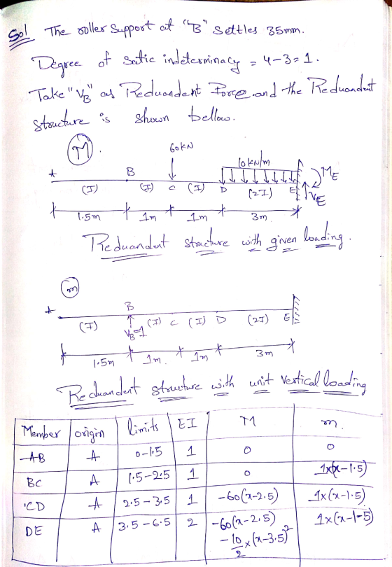
 #1) (65p.) Draw the Shear Force (V) and Bending Moment (M) diagrams of statically indeterminate beam shown in figure using “Force Method”. The (roller) support at “B” settles 35 mm. The moment of inertia is given by (I) for regions “AB”, “BC” and “CD”; however it is equal to (21) for the region “DE”. (“B” is the roller and “E” is the fixed type of support). [The flexural rigidity: EI=40000 kNm’] 60 KN 10 kN/m A B X (I) (I)...
#1) (65p.) Draw the Shear Force (V) and Bending Moment (M) diagrams of statically indeterminate beam...
 #1) (65p.) Draw the Shear Force (V) and Bending Moment (M) diagrams of statically indeterminate beam shown in figure using "Force Method”. The (roller) support at “B” settles 35 mm. The moment of inertia is given by (I) for regions "AB", "BC" and "CD"; however it is equal to (21) for the region “DE”. (“B” is the roller and “E” is the fixed type of support). [The flexural rigidity: EI=40000 kNm] 60 KN 10 kN/m B (21) 1.5 m 1...
#1) (65p.) Draw the Shear Force (V) and Bending Moment (M) diagrams of statically indeterminate beam...
 #1) (65p.) Draw the Shear Force (V) and Bending Moment (M) diagrams of statically indeterminate beam shown in figure using “Force Method”. The (roller) support at “B” settles 35 mm. The moment of inertia is given by (1) for regions "AB", "BC" and "CD"; however it is equal to (21) for the region “DE”. (“B” is the roller and "E" is the fixed type of support). [The flexural rigidity: EI=40000 kNm-] 60 KN 10 kN/m I. B (21) X 1.5...
#1) (65p.) Draw the Shear Force (V) and Bending Moment (M) diagrams of statically indeterminate beam...
 #1) (65p.) Draw the Shear Force (V) and Bending Moment (M) diagrams of statically indeterminate beam shown in figure using "Force Method". The (roller) support at "B" settles 35 mm. The moment of inertia is given by (1) for regions "AB", "BC" and "CD": however it is equal to (21) for the region "DE". ("B" is the roller and "E" is the fixed type of support). [The flexural rigidity: EI-40000 kNm] 60 KN 10 kN/m B L (21) 1.5 X...
#1) (65p.) Draw the Shear Force (V) and Bending Moment (M) diagrams of statically indeterminate beam...
 #1) (65p.) Draw the Shear Force (V) and Bending Moment (M) diagrams of statically indeterminate beam shown in figure using “Force Method”. The (roller) support at “B” settles 35 mm. The moment of inertia is given by (1) for regions “AB”, “BC” and “CD”; however it is equal to (21) for the region “DE”. (“B” is the roller and “E” is the fixed type of support). [The flexural rigidity: EI=40000 kNm?] 60 kN 10 kN/m 1 A B X (1)...
#1) (65p.) Draw the Shear Force (V) and Bending Moment (M) diagrams of statically indeterminate beam...
 #1) (65p.) Draw the Shear Force (V) and Bending Moment (M) diagrams of statically indeterminate beam shown in figure using “Force Method". The (roller) support at "B" settles 35 mm. The moment of inertia is given by (1) for regions "AB", "BC" and "CD"; however it is equal to (21) for the region "DE". ("B" is the roller and "E" is the fixed type of support). [The flexural rigidity: El-40000 kNm"] 60 KN 10 kN/m B (1) (1) D (21)...
Draw the Shear Force (V) and Bending Moment (MI) diagrams of statically indeterminate beam shown in...
 Draw the Shear Force (V) and Bending Moment (MI) diagrams of statically indeterminate beam shown in figure using “Force Method”. The (roller) support at "B" settles 35 mm. The moment of inertia is given by (1) for regions "AB", "BC" and "CD"; however it is equal to (21) for the region “DE”. ("B" is the roller and “E" is the fixed type of support). [The flexural rigidity: EI=40000 kNm] 60 KN y 10 kN/m A - Tu (21) 1.5m 11...
Problem 1: (30 points) Draw the shear force (V) and bending moment (M) diagrams for the...
 Problem 1: (30 points) Draw the shear force (V) and bending moment (M) diagrams for the beam AF given below. (B is a pin support, E is a roller support) Find the support reactions first. You are required to show the magnitude and location of all significant points. You don't have to find the equations defining the shear and moment diagrams unless necessary. However, indicate the order of all curves (e.g. 1" degree, 2nd degree, 3od degree). Ignore the depth...
Use the graphical method to construct the shear-force and bending-moment diagrams for the beam shown. Label...
 Use the graphical method to construct the shear-force and bending-moment diagrams for the beam shown. Label all significant points on each diagram and identify the maximum moments along with their respective locations. Additionally: (a) Determine V and M in the beam at a point located 1.50 m to the right of B. (b) Determine Vand M in the beam at a point located 1.25 m to the left of D. Leta - 3.0m, b = 6.1 m,w = 38 kN/m,...
4. For the beam and loading shown, draw the shear force and bending moment diagrams and...
 4. For the beam and loading shown, draw the shear force and bending moment diagrams and determine the maximum bending and shear force and their locations. 20 KN 40 KN B D 250 mm |--2.5 m- 3m-4-2 m 80 mm 5. For the beam and loading shown, draw the shear force and bending moment diagrams and determine the maximum bending and shear force and their locations. 50 KN
 #1) (65p.) Draw the Shear Force (V) and Bending Moment (M) diagrams of statically indeterminate beam shown in figure using “Force Method”. The (roller) support at “B” settles 35 mm. The moment of inertia is given by (I) for regions “AB”, “BC” and “CD”; however it is equal to (21) for the region “DE”. (“B” is the roller and “E” is the fixed type of support). [The flexural rigidity: EI=40000 kNm’] 60 KN 10 kN/m A B X (I) (I)...
 #1) (65p.) Draw the Shear Force (V) and Bending Moment (M) diagrams of statically indeterminate beam shown in figure using "Force Method”. The (roller) support at “B” settles 35 mm. The moment of inertia is given by (I) for regions "AB", "BC" and "CD"; however it is equal to (21) for the region “DE”. (“B” is the roller and “E” is the fixed type of support). [The flexural rigidity: EI=40000 kNm] 60 KN 10 kN/m B (21) 1.5 m 1...
 #1) (65p.) Draw the Shear Force (V) and Bending Moment (M) diagrams of statically indeterminate beam shown in figure using “Force Method”. The (roller) support at “B” settles 35 mm. The moment of inertia is given by (1) for regions "AB", "BC" and "CD"; however it is equal to (21) for the region “DE”. (“B” is the roller and "E" is the fixed type of support). [The flexural rigidity: EI=40000 kNm-] 60 KN 10 kN/m I. B (21) X 1.5...
 #1) (65p.) Draw the Shear Force (V) and Bending Moment (M) diagrams of statically indeterminate beam shown in figure using "Force Method". The (roller) support at "B" settles 35 mm. The moment of inertia is given by (1) for regions "AB", "BC" and "CD": however it is equal to (21) for the region "DE". ("B" is the roller and "E" is the fixed type of support). [The flexural rigidity: EI-40000 kNm] 60 KN 10 kN/m B L (21) 1.5 X...
 #1) (65p.) Draw the Shear Force (V) and Bending Moment (M) diagrams of statically indeterminate beam shown in figure using “Force Method”. The (roller) support at “B” settles 35 mm. The moment of inertia is given by (1) for regions “AB”, “BC” and “CD”; however it is equal to (21) for the region “DE”. (“B” is the roller and “E” is the fixed type of support). [The flexural rigidity: EI=40000 kNm?] 60 kN 10 kN/m 1 A B X (1)...
 #1) (65p.) Draw the Shear Force (V) and Bending Moment (M) diagrams of statically indeterminate beam shown in figure using “Force Method". The (roller) support at "B" settles 35 mm. The moment of inertia is given by (1) for regions "AB", "BC" and "CD"; however it is equal to (21) for the region "DE". ("B" is the roller and "E" is the fixed type of support). [The flexural rigidity: El-40000 kNm"] 60 KN 10 kN/m B (1) (1) D (21)...
 Draw the Shear Force (V) and Bending Moment (MI) diagrams of statically indeterminate beam shown in figure using “Force Method”. The (roller) support at "B" settles 35 mm. The moment of inertia is given by (1) for regions "AB", "BC" and "CD"; however it is equal to (21) for the region “DE”. ("B" is the roller and “E" is the fixed type of support). [The flexural rigidity: EI=40000 kNm] 60 KN y 10 kN/m A - Tu (21) 1.5m 11...
 Problem 1: (30 points) Draw the shear force (V) and bending moment (M) diagrams for the beam AF given below. (B is a pin support, E is a roller support) Find the support reactions first. You are required to show the magnitude and location of all significant points. You don't have to find the equations defining the shear and moment diagrams unless necessary. However, indicate the order of all curves (e.g. 1" degree, 2nd degree, 3od degree). Ignore the depth...
 Use the graphical method to construct the shear-force and bending-moment diagrams for the beam shown. Label all significant points on each diagram and identify the maximum moments along with their respective locations. Additionally: (a) Determine V and M in the beam at a point located 1.50 m to the right of B. (b) Determine Vand M in the beam at a point located 1.25 m to the left of D. Leta - 3.0m, b = 6.1 m,w = 38 kN/m,...
 4. For the beam and loading shown, draw the shear force and bending moment diagrams and determine the maximum bending and shear force and their locations. 20 KN 40 KN B D 250 mm |--2.5 m- 3m-4-2 m 80 mm 5. For the beam and loading shown, draw the shear force and bending moment diagrams and determine the maximum bending and shear force and their locations. 50 KN
Most questions answered within 3 hours.
-
Assume memory access is 10 units of time and disk access is
10000 units of time....
asked 7 minutes ago -
1. Are all good samples random?
2. Magazines often report surveys giving statistics such as “63%...
asked 29 minutes ago -
Under all the various types of market structures, firms
must eventually earn some economic profits for...
asked 15 minutes ago -
Consider the following fitness regime for a single locus trait
with two co-dominant alleles: w11 =...
asked 20 minutes ago -
A large cable company reports the following.
80% of its customers subscribe to its cable TV...
asked 35 minutes ago -
Please answer the question in brief.
Discuss the role of ERP in organizations. Are ERP tools...
asked 21 minutes ago -
Discuss the pros and cons of collaborative software such
as SameTime. Does it increase productivity? What...
asked 34 minutes ago -
Buying your in-laws a gift because it’s expected is
due to the ____________ motive of gift-giving....
asked 37 minutes ago -
Calculate the expected value, the variance, and the standard
deviation of the given random variable X....
asked 1 hour ago -
A hospital performs 100 surgeries per week. The probability that
complications after surgery occur is 10%....
asked 1 hour ago -
1 point) Given the significance level α=0.01 find the following:
(a) left-tailed z value z= (b)...
asked 1 hour ago -
Assuming you are the head of the software development unit at
Cyber.Soft, explain and justify why...
asked 44 minutes ago