
Homework Answers

Add Answer to:
force diagram. shear force 3. Obtain the reaction force of the statically determined beam shown in...
draw the 3. Obtain the reaction force of the statically determined beam shown Figs 3 (a),...
 draw the 3. Obtain the reaction force of the statically determined beam shown Figs 3 (a), (b) and bending moment diagram and shear force diagram. PL A 94 B.
beam For force are Figure statically determined shown below, the moment and sheal bending expressed function...
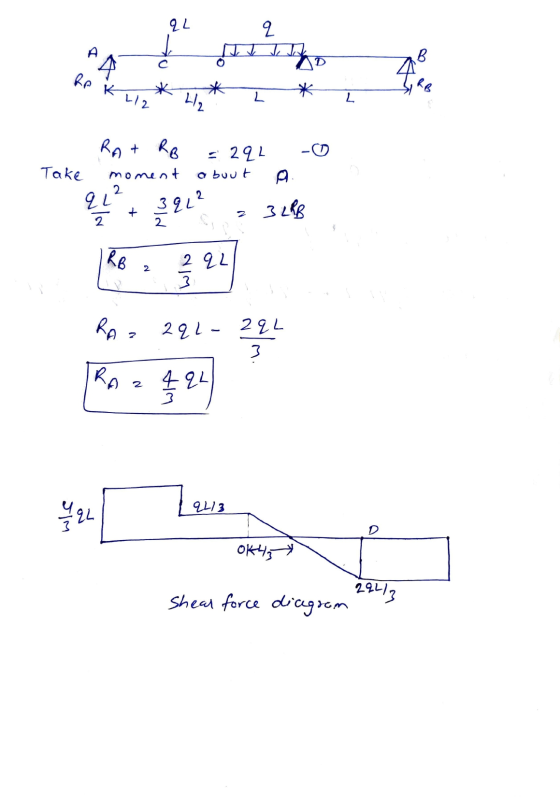
 beam For force are Figure statically determined shown below, the moment and sheal bending expressed function of the coordinate x. Drow momentum diagram and Shear as force diagram 9.L. 9 A B 4/2 1/2
Draw the shear force and bending-moment diagrams for the simply supported beam shown. Label each diagram...
 Draw the shear force and bending-moment diagrams for the simply
supported beam shown. Label each diagram with the corresponding
values
1. Draw the shear force and bending-moment diagrams for the simply supported beam shown. Label each diagram with the corresponding values. 3 Pe= 30 KN 4 m - m 3 m - C -40 kN - m
Draw the shear force and bending-moment diagrams for the simply
supported beam shown. Label each diagram with the corresponding
values
1. Draw the shear force and bending-moment diagrams for the simply supported beam shown. Label each diagram with the corresponding values. 3 Pe= 30 KN 4 m - m 3 m - C -40 kN - m
Problem #1 ) a) Draw the shear force and bending moment diagram for the shown beam....
 Problem #1 ) a) Draw the shear force and bending moment diagram for the shown beam. b) Determine the equations of the elastic curve using the x,and x2 coordinates. EI is constant. AJ p b
Draw the Shear Force (V) and Bending Moment (MI) diagrams of statically indeterminate beam shown in...
 Draw the Shear Force (V) and Bending Moment (MI) diagrams of statically indeterminate beam shown in figure using “Force Method”. The (roller) support at "B" settles 35 mm. The moment of inertia is given by (1) for regions "AB", "BC" and "CD"; however it is equal to (21) for the region “DE”. ("B" is the roller and “E" is the fixed type of support). [The flexural rigidity: EI=40000 kNm] 60 KN y 10 kN/m A - Tu (21) 1.5m 11...
#1) (65p.) Draw the Shear Force (V) and Bending Moment (M) diagrams of statically indeterminate beam...
 #1) (65p.) Draw the Shear Force (V) and Bending Moment (M) diagrams of statically indeterminate beam shown in figure using "Force Method". The (roller) support at "B" settles 35 mm. The moment of inertia is given by (1) for regions "AB", "BC" and "CD": however it is equal to (21) for the region "DE". ("B" is the roller and "E" is the fixed type of support). [The flexural rigidity: EI-40000 kNm] 60 KN 10 kN/m B L (21) 1.5 X...
For the beam below solve a) Reaction forces 20% b) Shear force diagram in Matlab or...
 For the beam below solve a) Reaction forces 20% b) Shear force diagram in Matlab or excel 20% e) Write a bending moment equation for each section of the beam in terms of x d) Bending moment diagram in Matlab or 40% excel 20% 30 kN 20 kN/m 10 kN (m) 2 8
For the beam below solve a) Reaction forces 20% b) Shear force diagram in Matlab or excel 20% e) Write a bending moment equation for each section...
For the beam below solve a) Reaction forces 20% b) Shear force diagram in Matlab or excel 20% e) Write a bending moment equation for each section of the beam in terms of x d) Bending moment diagram in Matlab or 40% excel 20% 30 kN 20 kN/m 10 kN (m) 2 8
For the beam below solve a) Reaction forces 20% b) Shear force diagram in Matlab or excel 20% e) Write a bending moment equation for each section...
For the beam shown in Fig. 9.3, draw the shear force and bending moment diagrams. Use...
 For the beam shown in Fig. 9.3, draw the shear force and bending moment diagrams. Use the area method that relies on the relationships between loading and shear force and between shear force and bending moment. Indicate the slope of the shear force diagram at locations A, B, C, and D using the load information in Fig. 9.3. Indicate the slope of the bending moment diagram at the same four locations using information from the shear force diagram. | 6...
(a) Sketch the shear force and bending moment diagram for the beam shown. Indicate the values and locations of maximum shear and moment.
 (a) Sketch the shear force and bending moment diagram for the beam shown. Indicate the values and locations of maximum shear and moment. (b) With the beam cross section shown, determine the maximum tensile stress, maximum compressive stress, and maximum transverse shear stress in the beam.
Problem 1: Draw the shear force and bending moment diagram for the beam shown below. (10)...
 Problem 1: Draw the shear force and bending moment diagram for the beam shown below. (10) Estimate the maximum bending stress located at section C (shown below). (10) Clearly identify the location on the cross section where the maximum bending stress is located. Is it tensile or compressive? Explain your answer.
 draw the 3. Obtain the reaction force of the statically determined beam shown Figs 3 (a), (b) and bending moment diagram and shear force diagram. PL A 94 B.
 beam For force are Figure statically determined shown below, the moment and sheal bending expressed function of the coordinate x. Drow momentum diagram and Shear as force diagram 9.L. 9 A B 4/2 1/2
 Draw the shear force and bending-moment diagrams for the simply
supported beam shown. Label each diagram with the corresponding
values
1. Draw the shear force and bending-moment diagrams for the simply supported beam shown. Label each diagram with the corresponding values. 3 Pe= 30 KN 4 m - m 3 m - C -40 kN - m
Draw the shear force and bending-moment diagrams for the simply
supported beam shown. Label each diagram with the corresponding
values
1. Draw the shear force and bending-moment diagrams for the simply supported beam shown. Label each diagram with the corresponding values. 3 Pe= 30 KN 4 m - m 3 m - C -40 kN - m
 Problem #1 ) a) Draw the shear force and bending moment diagram for the shown beam. b) Determine the equations of the elastic curve using the x,and x2 coordinates. EI is constant. AJ p b
 Draw the Shear Force (V) and Bending Moment (MI) diagrams of statically indeterminate beam shown in figure using “Force Method”. The (roller) support at "B" settles 35 mm. The moment of inertia is given by (1) for regions "AB", "BC" and "CD"; however it is equal to (21) for the region “DE”. ("B" is the roller and “E" is the fixed type of support). [The flexural rigidity: EI=40000 kNm] 60 KN y 10 kN/m A - Tu (21) 1.5m 11...
 #1) (65p.) Draw the Shear Force (V) and Bending Moment (M) diagrams of statically indeterminate beam shown in figure using "Force Method". The (roller) support at "B" settles 35 mm. The moment of inertia is given by (1) for regions "AB", "BC" and "CD": however it is equal to (21) for the region "DE". ("B" is the roller and "E" is the fixed type of support). [The flexural rigidity: EI-40000 kNm] 60 KN 10 kN/m B L (21) 1.5 X...
 For the beam below solve a) Reaction forces 20% b) Shear force diagram in Matlab or excel 20% e) Write a bending moment equation for each section of the beam in terms of x d) Bending moment diagram in Matlab or 40% excel 20% 30 kN 20 kN/m 10 kN (m) 2 8
For the beam below solve a) Reaction forces 20% b) Shear force diagram in Matlab or excel 20% e) Write a bending moment equation for each section...
For the beam below solve a) Reaction forces 20% b) Shear force diagram in Matlab or excel 20% e) Write a bending moment equation for each section of the beam in terms of x d) Bending moment diagram in Matlab or 40% excel 20% 30 kN 20 kN/m 10 kN (m) 2 8
For the beam below solve a) Reaction forces 20% b) Shear force diagram in Matlab or excel 20% e) Write a bending moment equation for each section...
 For the beam shown in Fig. 9.3, draw the shear force and bending moment diagrams. Use the area method that relies on the relationships between loading and shear force and between shear force and bending moment. Indicate the slope of the shear force diagram at locations A, B, C, and D using the load information in Fig. 9.3. Indicate the slope of the bending moment diagram at the same four locations using information from the shear force diagram. | 6...
 Problem 1: Draw the shear force and bending moment diagram for the beam shown below. (10) Estimate the maximum bending stress located at section C (shown below). (10) Clearly identify the location on the cross section where the maximum bending stress is located. Is it tensile or compressive? Explain your answer.
Most questions answered within 3 hours.
-
there is a function to create two random numbers between 1 and
25 and a function...
asked 2 minutes ago -
Part 1.C&A Fast Food has four activities in serving a
customer: greet customer, take order, process...
asked 2 minutes ago -
Which attribute allows you to specify a custom "thumbnail" for
multimedia elements?
asked 41 minutes ago -
How much 0.1200 M sodium hydroxide solution is need to titrate
14 mL of a 0.100...
asked 17 minutes ago -
An impulse is a change in momentum usually over
a short time. For which of the...
asked 21 minutes ago -
1a)When a 5000-kg roller coaster train full of riders approaches
the loading dock at a speed...
asked 41 minutes ago -
The Poseidon Swim Company produces swim trunks. The average
selling price for one of their swim...
asked 36 minutes ago -
If the elasticity of supply of a good is ∞, then its
A. supply curve is...
asked 23 minutes ago -
Write an application for the Shady Rest Hotel; the program
determines the price of a room....
asked 27 minutes ago -
USE THE FOLLOWING INFORMATION TO ANSWER THE NEXT (6)
QUESTIONS:
The following is a December 31,...
asked 43 minutes ago -
Suppose you plan to invest $5,000 each year (beginning at the
end of this year) into...
asked 34 minutes ago -
What is the cell potential of the following cell at 25
oC? Note Au is a...
asked 34 minutes ago