
Homework Answers
![yo(s) = -2 (+-5#te] -2 (1-6 t/RC) LICE) -2 (1-6th Jult Golt) = Yolt = T=RC) b X(t)= ult-3) 90-) = 2 YE=lvat t=6 sec ur C ult-](http://img.homeworklib.com/questions/1ed9c150-de59-11ea-80cd-ed1d4c293cea.png?x-oss-process=image/resize,w_560)
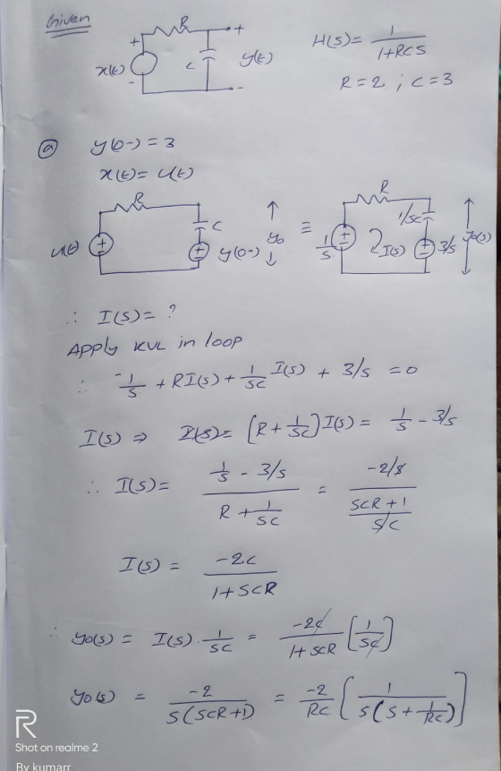
 By using Laplace transform we can get the
output based on the given initial conditions and calculated the
initial capacitor voltage .the voltage across capacitor is
-1.58V
By using Laplace transform we can get the
output based on the given initial conditions and calculated the
initial capacitor voltage .the voltage across capacitor is
-1.58V
Add Answer to:
1 4.4-1 The circuit shown in Fig. P4.4-1 has system function given by H(S) = Let...
Ω 1F + y(t) 2Ω 2Ω 1Ω Ω + 3Ω x(t) Ω Figure P4.4-14 4.4-14 Consider...
 Ω 1F + y(t) 2Ω 2Ω 1Ω Ω + 3Ω x(t) Ω Figure P4.4-14 4.4-14 Consider the op-amp circuit of Fig. P4.4-14. (a) Determine the standard-form transfer func- tion H(s) of this system. (b) Determine the standard-form constant coef- ficient linear differential equation descrip- tion of this circuit. (c) Using transform-domain techniques, deter- mine the circuit's zero-state response yzsr(t) to the input x(t) = e2tu(t + 1). (d) Using transform-domain techniques, deter- mine the circuit's zero-input response yzir (t) if...
1) An input step voltage Vin(t)=10 u(t) Volt is applied to the circuit shown below. The...
 1) An input step voltage Vin(t)=10 u(t) Volt is applied to the circuit shown below. The initial voltage on the capacitor is zero. Using Laplace transform techniques, calculate the resulting output voltage Vout(t). R1 R2 Vout 2000 Vin c1 1000 1uF R3 1000
subject: signals and systems 2. Consider the electric circuit shown in Fig. ??, L = 1H,...
 subject: signals and systems
2. Consider the electric circuit shown in Fig. ??, L = 1H, C = 1F. • Determine the differential equation that relates the input (t) to output y(t). Recall that ic(t) = C2C and vy(t) = • Find the characteristic equation for this circuit. • Determine the zero-input response given an initial capacitor voltage of one volt and an initial inductor current of zero ampere. That is, find yo(t) given uc(0) = 2V and iL(0) =...
subject: signals and systems
2. Consider the electric circuit shown in Fig. ??, L = 1H, C = 1F. • Determine the differential equation that relates the input (t) to output y(t). Recall that ic(t) = C2C and vy(t) = • Find the characteristic equation for this circuit. • Determine the zero-input response given an initial capacitor voltage of one volt and an initial inductor current of zero ampere. That is, find yo(t) given uc(0) = 2V and iL(0) =...
4.4-6 An LSB signal is demodulated coherently, as shown in Fig. P4.4-6. Unfortunately, because of the...
 4.4-6 An LSB signal is demodulated coherently, as shown in Fig. P4.4-6. Unfortunately, because of the transmission delay, the received signal carrier is not 2 cos Wet as sent, but rather, is 2 cos[wc + Aw)t + 8). The local oscillator is still cos wct. Show the following. (a) When 8 = 0, the output y(t) is the signal m(t) with all its spectral components shifted (offset) by Ao. Hint: Observe that the output y(t) is identical to the right-hand...
Problem 1 Given the circuit shown below in Fig. 1.1: Write the ordinary differential equation (ODE)...
 Problem 1 Given the circuit shown below in Fig. 1.1: Write the ordinary differential equation (ODE) for the capacitor voltage. Find the zero-state unit step responses of v(t) and i(t) if vs-u(t) V using each of the following three methods of solving the ODE: a. b. i. ii. Solve the ODE by integrating for the solution; Solve the ODE by assuming homogeneous and particular solutions; Solve the ODE by using the general form solution for a 1st order ODE. iii....
PROBLEM #2: In the circuit shown, suppose that R and C are given. The transfer function...
 PROBLEM #2: In the circuit shown, suppose that R and C are given. The transfer function of the circuit is G(s)== RCs +1 The impulse response of the circuit is g(t)== Let/RC ·u,(t). RC CV.CO Given that the input voltage is v;(t)=u,(t), determine the zero-state response v.(t) for t20 in two equivalent ways: (a) Use convolution. That is, compute the integral vo(t) = [ 8(t – T )v;()dt. (b) Use Laplace transforms. That is, compute vo(t) = ('{G(s)V;(s)}.
Problem#3 (16 points) Consider a system that has R(S) as the input and Y (S) as...
 Problem#3 (16 points) Consider a system that has R(S) as the input and Y (S) as the output. The transfer function is given by: Y(S) R(S) 45+12 What are the poles of the system? For r(t) output in the time-domain y(t) For r(t) = t, t output in the time-domain y(t) 1- 2- 1,t 0, use partial fraction expansion and inverse Laplace transform to find the 3- 0, use partial fraction expansion and inverse Laplace transform to find the
Problem 1: Find the Laplace transform X(s) of x(0)-6cos(Sr-3)u(t-3). 10 Problem 2: (a) Find the inverse...
 Problem 1: Find the Laplace transform X(s) of x(0)-6cos(Sr-3)u(t-3). 10 Problem 2: (a) Find the inverse Laplace transform h() of H(s)-10s+34 (Hint: use the Laplace transform pair for Decaying Sine or Generic Oscillatory Decay.) (b) Draw the corresponding direct form II block diagram of the system described by H(s) and (c) determine the corresponding differential equation. Problem 3: Using the unilateral Laplace transform, solve the following differential equation with the given initial condition: y)+5y(0) 2u), y(0)1 Problem 4: For the...
(15 pts) Given the following differential equations with the initial condition y(0) = 1, determine (1)...
 (15 pts) Given the following differential equations with the initial condition y(0) = 1, determine (1) the zero-input response yzi(t), (2) the zero-state response yzs (t) and (3) the total response y(t) for the input x(t) = e-fu(t) by using Laplace Transform. (5 pts) x+6y(t) = x - x() (1) Yzi(t) = (2) yzs(t) = (3) y(t) = (5 pts) (5 pts) 2. (10 pts) Given the following differential equations, find the total response y(t) if y(0) = 1 for...
For the system shown in Fig. 1, solve the following problems. (a) Find the transfer function, G(s...
 For the system shown in Fig. 1, solve the following problems. (a) Find the transfer function, G(s)X2 (s)/F(s) (b) Does the system oscillate with a unit step input (f (t))? Explain the reason (c) Decide if the system(x2 (t)) is stable with a unit step input (f (t))? Explain the reason 1. 320) 8 kg 2 N/m 4N-s/m 2N-s/m Fig. 1 2. There are two suspensions for a car as shown in Fig. 2 (a) Find the equations of each...
 Ω 1F + y(t) 2Ω 2Ω 1Ω Ω + 3Ω x(t) Ω Figure P4.4-14 4.4-14 Consider the op-amp circuit of Fig. P4.4-14. (a) Determine the standard-form transfer func- tion H(s) of this system. (b) Determine the standard-form constant coef- ficient linear differential equation descrip- tion of this circuit. (c) Using transform-domain techniques, deter- mine the circuit's zero-state response yzsr(t) to the input x(t) = e2tu(t + 1). (d) Using transform-domain techniques, deter- mine the circuit's zero-input response yzir (t) if...
 1) An input step voltage Vin(t)=10 u(t) Volt is applied to the circuit shown below. The initial voltage on the capacitor is zero. Using Laplace transform techniques, calculate the resulting output voltage Vout(t). R1 R2 Vout 2000 Vin c1 1000 1uF R3 1000
 subject: signals and systems
2. Consider the electric circuit shown in Fig. ??, L = 1H, C = 1F. • Determine the differential equation that relates the input (t) to output y(t). Recall that ic(t) = C2C and vy(t) = • Find the characteristic equation for this circuit. • Determine the zero-input response given an initial capacitor voltage of one volt and an initial inductor current of zero ampere. That is, find yo(t) given uc(0) = 2V and iL(0) =...
subject: signals and systems
2. Consider the electric circuit shown in Fig. ??, L = 1H, C = 1F. • Determine the differential equation that relates the input (t) to output y(t). Recall that ic(t) = C2C and vy(t) = • Find the characteristic equation for this circuit. • Determine the zero-input response given an initial capacitor voltage of one volt and an initial inductor current of zero ampere. That is, find yo(t) given uc(0) = 2V and iL(0) =...
 4.4-6 An LSB signal is demodulated coherently, as shown in Fig. P4.4-6. Unfortunately, because of the transmission delay, the received signal carrier is not 2 cos Wet as sent, but rather, is 2 cos[wc + Aw)t + 8). The local oscillator is still cos wct. Show the following. (a) When 8 = 0, the output y(t) is the signal m(t) with all its spectral components shifted (offset) by Ao. Hint: Observe that the output y(t) is identical to the right-hand...
 Problem 1 Given the circuit shown below in Fig. 1.1: Write the ordinary differential equation (ODE) for the capacitor voltage. Find the zero-state unit step responses of v(t) and i(t) if vs-u(t) V using each of the following three methods of solving the ODE: a. b. i. ii. Solve the ODE by integrating for the solution; Solve the ODE by assuming homogeneous and particular solutions; Solve the ODE by using the general form solution for a 1st order ODE. iii....
 PROBLEM #2: In the circuit shown, suppose that R and C are given. The transfer function of the circuit is G(s)== RCs +1 The impulse response of the circuit is g(t)== Let/RC ·u,(t). RC CV.CO Given that the input voltage is v;(t)=u,(t), determine the zero-state response v.(t) for t20 in two equivalent ways: (a) Use convolution. That is, compute the integral vo(t) = [ 8(t – T )v;()dt. (b) Use Laplace transforms. That is, compute vo(t) = ('{G(s)V;(s)}.
 Problem#3 (16 points) Consider a system that has R(S) as the input and Y (S) as the output. The transfer function is given by: Y(S) R(S) 45+12 What are the poles of the system? For r(t) output in the time-domain y(t) For r(t) = t, t output in the time-domain y(t) 1- 2- 1,t 0, use partial fraction expansion and inverse Laplace transform to find the 3- 0, use partial fraction expansion and inverse Laplace transform to find the
 Problem 1: Find the Laplace transform X(s) of x(0)-6cos(Sr-3)u(t-3). 10 Problem 2: (a) Find the inverse Laplace transform h() of H(s)-10s+34 (Hint: use the Laplace transform pair for Decaying Sine or Generic Oscillatory Decay.) (b) Draw the corresponding direct form II block diagram of the system described by H(s) and (c) determine the corresponding differential equation. Problem 3: Using the unilateral Laplace transform, solve the following differential equation with the given initial condition: y)+5y(0) 2u), y(0)1 Problem 4: For the...
 (15 pts) Given the following differential equations with the initial condition y(0) = 1, determine (1) the zero-input response yzi(t), (2) the zero-state response yzs (t) and (3) the total response y(t) for the input x(t) = e-fu(t) by using Laplace Transform. (5 pts) x+6y(t) = x - x() (1) Yzi(t) = (2) yzs(t) = (3) y(t) = (5 pts) (5 pts) 2. (10 pts) Given the following differential equations, find the total response y(t) if y(0) = 1 for...
 For the system shown in Fig. 1, solve the following problems. (a) Find the transfer function, G(s)X2 (s)/F(s) (b) Does the system oscillate with a unit step input (f (t))? Explain the reason (c) Decide if the system(x2 (t)) is stable with a unit step input (f (t))? Explain the reason 1. 320) 8 kg 2 N/m 4N-s/m 2N-s/m Fig. 1 2. There are two suspensions for a car as shown in Fig. 2 (a) Find the equations of each...
Most questions answered within 3 hours.
-
if a firm producing 100 units at $5.00 each experience
an 80% experience curve, what will...
asked 25 minutes ago -
A solid, uniform disk of radius 0.250 m and mass 53.7 kg rolls
down a ramp...
asked 2 hours ago -
Given the following table of high speed internet access vs.
annual home income:
Home Income
%...
asked 3 hours ago -
A baseball batter hits a 0.145kg baseball straight up into the
air. The baseball leaves the...
asked 3 hours ago -
An FM modulator is tested using
single-tone baseband signal with frequency of 50kHz and a sprectrum...
asked 4 hours ago -
Write the ionic equations for the first stage of salts
hydrolysis.
Anion, Cation?
Na2S
NiSO4
K2SO4...
asked 5 hours ago -
suppose there is a normally distributed population with a mean of
250 and a standard deviation...
asked 6 hours ago -
Question Three
Suppose you as project manager are using the Waterfall
development methodology on a large...
asked 7 hours ago -
Which statement is not true about welfare in Canada?
A.Benefits typically vary based on one's ability...
asked 7 hours ago -
Please help me with FLOWCHART and UML diagram for class,
thank you!
#include <iostream>
#include <fstream>...
asked 8 hours ago -
3. Describe the “logic circuit” of the Lac operon. Which
proteins are bound or not to...
asked 8 hours ago -
Ayesha’s adjusted gross income is $60,000 in 2019. She donated a
piece of artwork with a...
asked 8 hours ago