


2. There are two suspensions for a car as shown in Fig. 2 (a) Find the equations of each motion and transfer functions (FC),T()) (b) With m - 1 (kg),c4(N/m/s), k 20(N/m) and a unit step input (y(t) - us(t)), find 1(s) X2 x1(t) and x2) (c)(i) Draw the unit step input, x(t) and x2(t) in a figure by using Matlab (ii) Draw the unit step input and x1(t) with c= 0,4,9 in a figure by using Matlab X1(t) x2(t) Fig. 2. Two suspensions
Consider a lever system as shown in Fig. 3. 3. (a) Derive the equation of motion and the traP), assuming small e(s) F(s) displacements and the zero initial conditions. (b) When does the lever system oscillate? し2 Fig. 3
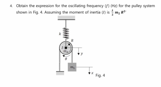
4. Obtain the expression for the oscillating frequency (f) (Hz) for the pulley system shown in Fig. 4. Assuming the moment of inertia (I) is m2 R2' ,1 Fig. 4
5. For the rotational mechanical system shown in Fig. 5, find the transfer functions T(s) 1 N-m/rad Tt) θ2(1) I kg-m2 1 N-m-s/rad 1 N-m-s/rad 1 N-m-s/rad Fig. 5
θ2(s)/T(s), for the rotational mechanical system Find the transfer function (G(s) shown in Fig6 500 N-m-s/rad 100kg-m2 Na 25 T0) 3 kg-m2 00 N-m/rad 200kg-m Fig. 6
7. In the system shown in Fig. 5, the inertia, J, of radius, r, is constrained to move only about the stationary axis A. A viscous damping force of translational value f exists between the bodies J and M. If an external force, f(t), is applied to the mass, find the transfer function, G(s) (s)/F(s). fRt) Fig. 5
8. There is an electromagnetic speaker shown in Fig. 6. Speaker enclosure Magnet Coil Fig. 5 (a) Find the transfer function (X/V) relating the diaphragm displacement (x) to the applied voltage (v), as considering the following conditions 1) The diaphragm can be schematically modeled to a mass-spring-damper mechanical system with a spring (k), a damper (c), and a mass (m). 2) The voice coil motor generates a force based on the Lorentz force (f nBil Kyi) and can be schematically modeled to an electrical system with a resistor (R), a inductor (L), and an -EMF voltage. Kf: force constant, K:-EMF constant (b) As ignoring the inductance of the voice coil motor and assuming all constant values to 1, obtain the displacement (x(t)) with an unit step input (u()) as the input voltage (v).
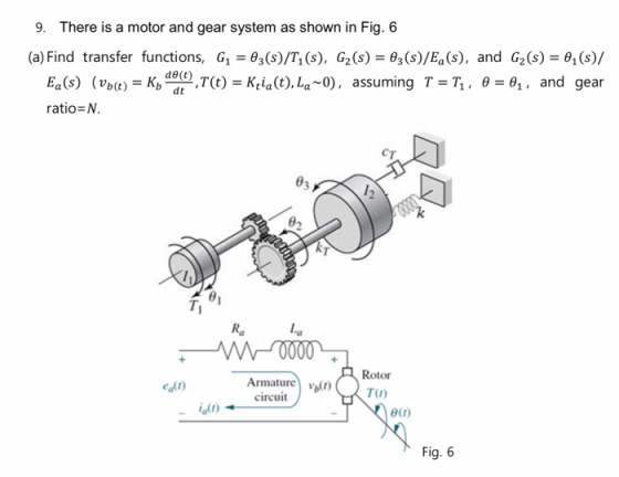
9. There is a motor and gear system as shown in Fig. 6 (a) Find transfer functions, G1-θ3(s)/7, (s), G2(s)-θ3(s)/Ea (s), and G2 (s)-0,(s)/ (Up(t,-Kbddtt),T(t)-Kia(t), La ~0), assuming θ-0,, and Ea(s) T, gear ratio-N. ст θ3 02 La Ra Rotor Armature vT) ealt) circuit ialo θ(r) Fig. 6
10. Consider the system shown in Fig. 7 (a) Obtain the transfer function (G(s)-x(s)%, (s). eal Motor N 10 J-1 kg-m2 RN-m-s/rad N2 -20 Ideal gear 1:1 Radius 2 m M-1 kg For the motor: ru) Da 1 N-m-s/rad Ky = 1 V-s/rad Fig. 7
Homework Answers


Add Answer to:
For the system shown in Fig. 1, solve the following problems. (a) Find the transfer function, G(s...
Question 3 Find the transfer function, G(s) s) / T(s), for the rotational mechanical system in...
 Question 3 Find the transfer function, G(s) s) / T(s), for the rotational mechanical system in Fig. Q3 below. The gears have inertia and bearing friction as shown. (20 marks) 3 Nm/rad 2 Nms/rad + 1 kg/m? N3 = 100 N2 = 100 T(t) N4 = 20 N = 20 0.04 Nms/rad Fig. Q3
θ2(s)/T(s) for the following rotational mechanical system Problem 4: Find the transfer function G(s) TO) N1...
 θ2(s)/T(s) for the following rotational mechanical system Problem 4: Find the transfer function G(s) TO) N1 = 4 Di 1 N-m-s/rad N2 121 kg-m2 N3-4 D2-2 N-m-s/rad K 64 N-m/rad- N4 16 D3 32 N-m-s/rad -16 kg-m2 000
please show steps For the system shown in the figure. a. Find the transfer function 0,(s)/T(S)....
 please show steps
For the system shown in the figure. a. Find the transfer function 0,(s)/T(S). b. Find the damping Dyo yield a 20% gvershoot in output angular displacement for a step torque input. N =25 kg-r W3 10 N2=5 D N-m/rad N4 5 0000
For the system shown in the figure. a. Find the transfer function 0,(s)/T(S). b. Find the damping Dyo yield a 20% gvershoot in output angular displacement for a step torque input. N =25 kg-r W3...
please show steps
For the system shown in the figure. a. Find the transfer function 0,(s)/T(S). b. Find the damping Dyo yield a 20% gvershoot in output angular displacement for a step torque input. N =25 kg-r W3 10 N2=5 D N-m/rad N4 5 0000
For the system shown in the figure. a. Find the transfer function 0,(s)/T(S). b. Find the damping Dyo yield a 20% gvershoot in output angular displacement for a step torque input. N =25 kg-r W3...
6. For the following mechanical system: a) Find a mathematical model b) Find the transfer functio...
 6. For the following mechanical system: a) Find a mathematical model b) Find the transfer function, G(s) = c Find impulse, step and ramp response by using MATLAB functions d) Find harmonic response by using MATLAB SIMULINK T(s) 2 N-m-s/rad 2 N-m/rad N2-20 T0) l kg-m2 N3-40 010 N1-5 N4-10 0.02 N-m-s/radl
6. For the following mechanical system: a) Find a mathematical model b) Find the transfer function, G(s) = c Find impulse, step and ramp response by using MATLAB...
6. For the following mechanical system: a) Find a mathematical model b) Find the transfer function, G(s) = c Find impulse, step and ramp response by using MATLAB functions d) Find harmonic response by using MATLAB SIMULINK T(s) 2 N-m-s/rad 2 N-m/rad N2-20 T0) l kg-m2 N3-40 010 N1-5 N4-10 0.02 N-m-s/radl
6. For the following mechanical system: a) Find a mathematical model b) Find the transfer function, G(s) = c Find impulse, step and ramp response by using MATLAB...
1. Obtain the transfer function G(s)-20 Consider the system of Figure 1. Obtain the transfer func...
 1. Obtain the transfer function G(s)-20 Consider the system of Figure 1. Obtain the transfer function G (s) - of the system in Figure 1 (clearly show the derivation of the model) Question 1.(15) Consider the system of Figure T(s) TO) J1 2 kg-m D1 1 N-m-s/rad J2-1 kg-m2 D2 2 N-m-s/rad K = 64 N-m/rad J-16 kg-m2 D3 32 N-m-s/rad Figure 1
1. Obtain the transfer function G(s)-20 Consider the system of Figure 1. Obtain the transfer function G...
1. Obtain the transfer function G(s)-20 Consider the system of Figure 1. Obtain the transfer function G (s) - of the system in Figure 1 (clearly show the derivation of the model) Question 1.(15) Consider the system of Figure T(s) TO) J1 2 kg-m D1 1 N-m-s/rad J2-1 kg-m2 D2 2 N-m-s/rad K = 64 N-m/rad J-16 kg-m2 D3 32 N-m-s/rad Figure 1
1. Obtain the transfer function G(s)-20 Consider the system of Figure 1. Obtain the transfer function G...
Question 1 Figure Q1 shows a mechanical system. The system input is T) and output is supposed to ...
 Please write down the steps by steps solution, thank
you!
Question 1 Figure Q1 shows a mechanical system. The system input is T) and output is supposed to be 0. Please find the transfer function from T to θ 3, and discuss the stability of the system if the input is a unit impulse signal. (30 marks) To 01(t) 01t) I kg-m2 N 10 030) N2 100 100 kg-m2 100 N-m/rad 100 N-m-s/rad Figure Q1
Question 1 Figure Q1 shows...
Please write down the steps by steps solution, thank
you!
Question 1 Figure Q1 shows a mechanical system. The system input is T) and output is supposed to be 0. Please find the transfer function from T to θ 3, and discuss the stability of the system if the input is a unit impulse signal. (30 marks) To 01(t) 01t) I kg-m2 N 10 030) N2 100 100 kg-m2 100 N-m/rad 100 N-m-s/rad Figure Q1
Question 1 Figure Q1 shows...
4, (a) (20%) Find the transfer function Xi(s) / U(s) for the system shown in Fig....
 4, (a) (20%) Find the transfer function Xi(s) / U(s) for the system shown in Fig. 2. (b) (20%) obtain a state-space model of the system shown in Fig. 2, where u is the input and x is the output. k2 kj m2 b2
Can you show step by step calculation. Thank you Find the transfer function X (5) F(s)...
 Can you show step by step calculation. Thank
you
Find the transfer function X (5) F(s) and X2() for the mechanical system below F(8) X (1) Ki = 4 N/m K2 = 5 N/m 0000 0000 tvi = 3 N-s/m My = 1 kg fv2 = 3 N-s/m fin 2 N-s/m M2 = 2 kg fv3 =
Can you show step by step calculation. Thank
you
Find the transfer function X (5) F(s) and X2() for the mechanical system below F(8) X (1) Ki = 4 N/m K2 = 5 N/m 0000 0000 tvi = 3 N-s/m My = 1 kg fv2 = 3 N-s/m fin 2 N-s/m M2 = 2 kg fv3 =
4. Determine the transfer function G(s) = for the system shown below. F(s) K1 = 4...
 4. Determine the transfer function G(s) = for the system shown below. F(s) K1 = 4 N/m + X(t) →xj(t) K = 5 N/m 0000 M = 1 kg 1v2 = 3 N-s/m M2 = 2 kg f(t) HHH
Problem 2 Determine the transfer function 01(s)/M(s) for the shaft-gear mechanical system in the figure, where...
 Problem 2 Determine the transfer function 01(s)/M(s) for the shaft-gear mechanical system in the figure, where 1(s) and Ms) are the Laplace transforms of the angle 01(t) and of the moment m(t). Use the time-domain mathematical model of this system. Known are J1, ki, J2, c, k2, Ni and N2. N. 1000 0,m 0 000 N Problem 3 By using the transfer function 1(s)/Ms), determined in Problem 2, calculate and plot 01(t) using the step input command of MATLAB. Known...
 Question 3 Find the transfer function, G(s) s) / T(s), for the rotational mechanical system in Fig. Q3 below. The gears have inertia and bearing friction as shown. (20 marks) 3 Nm/rad 2 Nms/rad + 1 kg/m? N3 = 100 N2 = 100 T(t) N4 = 20 N = 20 0.04 Nms/rad Fig. Q3
 θ2(s)/T(s) for the following rotational mechanical system Problem 4: Find the transfer function G(s) TO) N1 = 4 Di 1 N-m-s/rad N2 121 kg-m2 N3-4 D2-2 N-m-s/rad K 64 N-m/rad- N4 16 D3 32 N-m-s/rad -16 kg-m2 000
 please show steps
For the system shown in the figure. a. Find the transfer function 0,(s)/T(S). b. Find the damping Dyo yield a 20% gvershoot in output angular displacement for a step torque input. N =25 kg-r W3 10 N2=5 D N-m/rad N4 5 0000
For the system shown in the figure. a. Find the transfer function 0,(s)/T(S). b. Find the damping Dyo yield a 20% gvershoot in output angular displacement for a step torque input. N =25 kg-r W3...
please show steps
For the system shown in the figure. a. Find the transfer function 0,(s)/T(S). b. Find the damping Dyo yield a 20% gvershoot in output angular displacement for a step torque input. N =25 kg-r W3 10 N2=5 D N-m/rad N4 5 0000
For the system shown in the figure. a. Find the transfer function 0,(s)/T(S). b. Find the damping Dyo yield a 20% gvershoot in output angular displacement for a step torque input. N =25 kg-r W3...
 6. For the following mechanical system: a) Find a mathematical model b) Find the transfer function, G(s) = c Find impulse, step and ramp response by using MATLAB functions d) Find harmonic response by using MATLAB SIMULINK T(s) 2 N-m-s/rad 2 N-m/rad N2-20 T0) l kg-m2 N3-40 010 N1-5 N4-10 0.02 N-m-s/radl
6. For the following mechanical system: a) Find a mathematical model b) Find the transfer function, G(s) = c Find impulse, step and ramp response by using MATLAB...
6. For the following mechanical system: a) Find a mathematical model b) Find the transfer function, G(s) = c Find impulse, step and ramp response by using MATLAB functions d) Find harmonic response by using MATLAB SIMULINK T(s) 2 N-m-s/rad 2 N-m/rad N2-20 T0) l kg-m2 N3-40 010 N1-5 N4-10 0.02 N-m-s/radl
6. For the following mechanical system: a) Find a mathematical model b) Find the transfer function, G(s) = c Find impulse, step and ramp response by using MATLAB...
 1. Obtain the transfer function G(s)-20 Consider the system of Figure 1. Obtain the transfer function G (s) - of the system in Figure 1 (clearly show the derivation of the model) Question 1.(15) Consider the system of Figure T(s) TO) J1 2 kg-m D1 1 N-m-s/rad J2-1 kg-m2 D2 2 N-m-s/rad K = 64 N-m/rad J-16 kg-m2 D3 32 N-m-s/rad Figure 1
1. Obtain the transfer function G(s)-20 Consider the system of Figure 1. Obtain the transfer function G...
1. Obtain the transfer function G(s)-20 Consider the system of Figure 1. Obtain the transfer function G (s) - of the system in Figure 1 (clearly show the derivation of the model) Question 1.(15) Consider the system of Figure T(s) TO) J1 2 kg-m D1 1 N-m-s/rad J2-1 kg-m2 D2 2 N-m-s/rad K = 64 N-m/rad J-16 kg-m2 D3 32 N-m-s/rad Figure 1
1. Obtain the transfer function G(s)-20 Consider the system of Figure 1. Obtain the transfer function G...
 Please write down the steps by steps solution, thank
you!
Question 1 Figure Q1 shows a mechanical system. The system input is T) and output is supposed to be 0. Please find the transfer function from T to θ 3, and discuss the stability of the system if the input is a unit impulse signal. (30 marks) To 01(t) 01t) I kg-m2 N 10 030) N2 100 100 kg-m2 100 N-m/rad 100 N-m-s/rad Figure Q1
Question 1 Figure Q1 shows...
Please write down the steps by steps solution, thank
you!
Question 1 Figure Q1 shows a mechanical system. The system input is T) and output is supposed to be 0. Please find the transfer function from T to θ 3, and discuss the stability of the system if the input is a unit impulse signal. (30 marks) To 01(t) 01t) I kg-m2 N 10 030) N2 100 100 kg-m2 100 N-m/rad 100 N-m-s/rad Figure Q1
Question 1 Figure Q1 shows...
 4, (a) (20%) Find the transfer function Xi(s) / U(s) for the system shown in Fig. 2. (b) (20%) obtain a state-space model of the system shown in Fig. 2, where u is the input and x is the output. k2 kj m2 b2
 Can you show step by step calculation. Thank
you
Find the transfer function X (5) F(s) and X2() for the mechanical system below F(8) X (1) Ki = 4 N/m K2 = 5 N/m 0000 0000 tvi = 3 N-s/m My = 1 kg fv2 = 3 N-s/m fin 2 N-s/m M2 = 2 kg fv3 =
Can you show step by step calculation. Thank
you
Find the transfer function X (5) F(s) and X2() for the mechanical system below F(8) X (1) Ki = 4 N/m K2 = 5 N/m 0000 0000 tvi = 3 N-s/m My = 1 kg fv2 = 3 N-s/m fin 2 N-s/m M2 = 2 kg fv3 =
 4. Determine the transfer function G(s) = for the system shown below. F(s) K1 = 4 N/m + X(t) →xj(t) K = 5 N/m 0000 M = 1 kg 1v2 = 3 N-s/m M2 = 2 kg f(t) HHH
 Problem 2 Determine the transfer function 01(s)/M(s) for the shaft-gear mechanical system in the figure, where 1(s) and Ms) are the Laplace transforms of the angle 01(t) and of the moment m(t). Use the time-domain mathematical model of this system. Known are J1, ki, J2, c, k2, Ni and N2. N. 1000 0,m 0 000 N Problem 3 By using the transfer function 1(s)/Ms), determined in Problem 2, calculate and plot 01(t) using the step input command of MATLAB. Known...
Most questions answered within 3 hours.
-
What is the pH of a 0.200 M solution of sulfurous acid? Given:
Ka1 = 1.70×10⁻²,...
asked 9 minutes ago -
Sociologists have conducted much interesting research on gender
stereotypes in American society. A curious aspect of...
asked 15 minutes ago -
1. Based on your results, calculate how many kilograms of plant
material you would need to...
asked 18 minutes ago -
Sample (taken every two minutes)
Angle of Rotation
0
102.9
2
104.2
4
106.2
6
104.8*...
asked 15 minutes ago -
Adrian's utilities of two consumption bundles are 50 and 100,
respectively. This implies that A. Adrian...
asked 25 minutes ago -
1. A 24.9 mL sample of 0.332 M
methylamine,
CH3NH2, is titrated with
0.264 M perchloric...
asked 27 minutes ago -
You're working as a security analyst for a small company that
doesn't have the resources of...
asked 31 minutes ago -
As the project manager of a large project, you have just
completed the Estimate Costs process....
asked 33 minutes ago -
Suppose that a budget equation is goven by p1x1 + p2x2
= m. The government decides...
asked 35 minutes ago -
Beowulf is a specific form of epic--identify
this form. Consider one of the most significant and...
asked 1 hour ago -
Retroviruses use the enzyme reverse transcriptase to
Retroviruses use the enzyme reverse transcriptase to
synthesize a...
asked 1 hour ago -
A mixture initially contains A, B, and C in the following
concentrations: [A] = 0.400 M...
asked 1 hour ago