
Homework Answers
 Part C&D:
Programming code Using MATLAB:
clc;
clear all;
close all;
sys=tf([1],[1,1.98,2]); ############## Defining G(s)
figure(1) ######## Plot for impulse response
impulse(sys)
figure(2)#####Plot for step response
step(sys)
########## Plotting ramp response using 'lsim' command
t=0:0.1:10;
ramp=t;
######## obtaining the response 'r' of the model for input
'ramp'
[r,t]=lsim(sys,ramp,t);
%plotting 'r' vs. time
figure(3)
plot(t,r)
title('Ramp Response')
xlabel('Time (seconds)')
ylabel('Amplitude')
######### harmonic response using 'bode' command
figure(4)
bode(sys)
MATLAB O/P:
Impulse Response:: Step response:

Ramp Response:
 Bode Diagram:

If you have any doubt about Matlab Code, Comment below
Add Answer to:
6. For the following mechanical system: a) Find a mathematical model b) Find the transfer functio...
θ2(s)/T(s) for the following rotational mechanical system Problem 4: Find the transfer function G(s) TO) N1...
 θ2(s)/T(s) for the following rotational mechanical system Problem 4: Find the transfer function G(s) TO) N1 = 4 Di 1 N-m-s/rad N2 121 kg-m2 N3-4 D2-2 N-m-s/rad K 64 N-m/rad- N4 16 D3 32 N-m-s/rad -16 kg-m2 000
Question 3 Find the transfer function, G(s) s) / T(s), for the rotational mechanical system in...
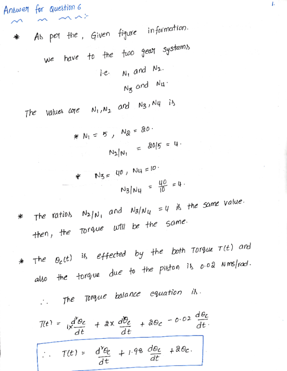
 Question 3 Find the transfer function, G(s) s) / T(s), for the rotational mechanical system in Fig. Q3 below. The gears have inertia and bearing friction as shown. (20 marks) 3 Nm/rad 2 Nms/rad + 1 kg/m? N3 = 100 N2 = 100 T(t) N4 = 20 N = 20 0.04 Nms/rad Fig. Q3
Problem 2 Determine the transfer function 01(s)/M(s) for the shaft-gear mechanical system in the figure, where...
 Problem 2 Determine the transfer function 01(s)/M(s) for the shaft-gear mechanical system in the figure, where 1(s) and Ms) are the Laplace transforms of the angle 01(t) and of the moment m(t). Use the time-domain mathematical model of this system. Known are J1, ki, J2, c, k2, Ni and N2. N. 1000 0,m 0 000 N Problem 3 By using the transfer function 1(s)/Ms), determined in Problem 2, calculate and plot 01(t) using the step input command of MATLAB. Known...
For the system shown in Fig. 1, solve the following problems. (a) Find the transfer function, G(s...
 For the system shown in Fig. 1, solve the following problems. (a) Find the transfer function, G(s)X2 (s)/F(s) (b) Does the system oscillate with a unit step input (f (t))? Explain the reason (c) Decide if the system(x2 (t)) is stable with a unit step input (f (t))? Explain the reason 1. 320) 8 kg 2 N/m 4N-s/m 2N-s/m Fig. 1 2. There are two suspensions for a car as shown in Fig. 2 (a) Find the equations of each...
Question 1 Figure Q1 shows a mechanical system. The system input is T) and output is supposed to ...
 Please write down the steps by steps solution, thank
you!
Question 1 Figure Q1 shows a mechanical system. The system input is T) and output is supposed to be 0. Please find the transfer function from T to θ 3, and discuss the stability of the system if the input is a unit impulse signal. (30 marks) To 01(t) 01t) I kg-m2 N 10 030) N2 100 100 kg-m2 100 N-m/rad 100 N-m-s/rad Figure Q1
Question 1 Figure Q1 shows...
Please write down the steps by steps solution, thank
you!
Question 1 Figure Q1 shows a mechanical system. The system input is T) and output is supposed to be 0. Please find the transfer function from T to θ 3, and discuss the stability of the system if the input is a unit impulse signal. (30 marks) To 01(t) 01t) I kg-m2 N 10 030) N2 100 100 kg-m2 100 N-m/rad 100 N-m-s/rad Figure Q1
Question 1 Figure Q1 shows...
IL IULIUCI. (Q3) Consider below rotational mechanical system. Find the transfer function between 02(s) and T(s),...
 IL IULIUCI. (Q3) Consider below rotational mechanical system. Find the transfer function between 02(s) and T(s), that is find G(s) = 0; (5) T(s) en(t) T(t) 1) N1=20 W 1 N3=30 02(t) 450 kg.m? N2=100 225 N.m/rad --00004 Ny=90 5 N.m.s/rad 3 N.m.s/rad
' 1. Review Question a) Name three applications for feedback control systems. b) Functionally, ho...
 ' 1. Review Question a) Name three applications for feedback control systems. b) Functionally, how do closed-loop systems differ from open-loop systems? c) Name the three major design criteria for control systems. d) Name the performance specification for first-order systems. e) Briefly describe how the zeros of the open-loop system affect the root locus and the transient response. What does the Routh-Hurwitz criterion tell us? f) 2. Given the electric network shown in Figure. a) Write the differential equation for...
please show steps For the system shown in the figure. a. Find the transfer function 0,(s)/T(S)....
 please show steps
For the system shown in the figure. a. Find the transfer function 0,(s)/T(S). b. Find the damping Dyo yield a 20% gvershoot in output angular displacement for a step torque input. N =25 kg-r W3 10 N2=5 D N-m/rad N4 5 0000
For the system shown in the figure. a. Find the transfer function 0,(s)/T(S). b. Find the damping Dyo yield a 20% gvershoot in output angular displacement for a step torque input. N =25 kg-r W3...
please show steps
For the system shown in the figure. a. Find the transfer function 0,(s)/T(S). b. Find the damping Dyo yield a 20% gvershoot in output angular displacement for a step torque input. N =25 kg-r W3 10 N2=5 D N-m/rad N4 5 0000
For the system shown in the figure. a. Find the transfer function 0,(s)/T(S). b. Find the damping Dyo yield a 20% gvershoot in output angular displacement for a step torque input. N =25 kg-r W3...
Question 1-4 is about the following mechanical system: Data: ki-20 [N/m] b-2 [Ns/m] k2# 10 [N/m] m2 At) mi Question 1 X...
 Question 1-4 is about the following mechanical system: Data: ki-20 [N/m] b-2 [Ns/m] k2# 10 [N/m] m2 At) mi Question 1 X1(s) Develop the symbolic transfer function G1(s)2 F(s) 1.1 Determine the differential equation, that this transfer function describe 1.2 Question 2 Sketch the step response for G1(s), using Matlab and explain the process 2.1 Sketch the pole /zero diagram for the transfer function G1(s) and reflect on the relation between the step response and the pole /zero diagram 2.2...
7.22 A simple 1-DOF mechanical system has the following transfer function Y(s) 0.25 U(s) s +2s...
 7.22 A simple 1-DOF mechanical system has the following transfer function Y(s) 0.25 U(s) s +2s +9 where the position of the mass y0) is in meters. The system is initially at rest, y(O) (0) 0, and the applied force is a step function u(t0 4N Copyrighto Problems 243 a. Accurately sketch the system response y() and label all important performance criteria on your sketch b. Use MATLAB or Simulink to verify your sketch in part (a). Plot y(o) from...
 θ2(s)/T(s) for the following rotational mechanical system Problem 4: Find the transfer function G(s) TO) N1 = 4 Di 1 N-m-s/rad N2 121 kg-m2 N3-4 D2-2 N-m-s/rad K 64 N-m/rad- N4 16 D3 32 N-m-s/rad -16 kg-m2 000
 Question 3 Find the transfer function, G(s) s) / T(s), for the rotational mechanical system in Fig. Q3 below. The gears have inertia and bearing friction as shown. (20 marks) 3 Nm/rad 2 Nms/rad + 1 kg/m? N3 = 100 N2 = 100 T(t) N4 = 20 N = 20 0.04 Nms/rad Fig. Q3
 Problem 2 Determine the transfer function 01(s)/M(s) for the shaft-gear mechanical system in the figure, where 1(s) and Ms) are the Laplace transforms of the angle 01(t) and of the moment m(t). Use the time-domain mathematical model of this system. Known are J1, ki, J2, c, k2, Ni and N2. N. 1000 0,m 0 000 N Problem 3 By using the transfer function 1(s)/Ms), determined in Problem 2, calculate and plot 01(t) using the step input command of MATLAB. Known...
 For the system shown in Fig. 1, solve the following problems. (a) Find the transfer function, G(s)X2 (s)/F(s) (b) Does the system oscillate with a unit step input (f (t))? Explain the reason (c) Decide if the system(x2 (t)) is stable with a unit step input (f (t))? Explain the reason 1. 320) 8 kg 2 N/m 4N-s/m 2N-s/m Fig. 1 2. There are two suspensions for a car as shown in Fig. 2 (a) Find the equations of each...
 Please write down the steps by steps solution, thank
you!
Question 1 Figure Q1 shows a mechanical system. The system input is T) and output is supposed to be 0. Please find the transfer function from T to θ 3, and discuss the stability of the system if the input is a unit impulse signal. (30 marks) To 01(t) 01t) I kg-m2 N 10 030) N2 100 100 kg-m2 100 N-m/rad 100 N-m-s/rad Figure Q1
Question 1 Figure Q1 shows...
Please write down the steps by steps solution, thank
you!
Question 1 Figure Q1 shows a mechanical system. The system input is T) and output is supposed to be 0. Please find the transfer function from T to θ 3, and discuss the stability of the system if the input is a unit impulse signal. (30 marks) To 01(t) 01t) I kg-m2 N 10 030) N2 100 100 kg-m2 100 N-m/rad 100 N-m-s/rad Figure Q1
Question 1 Figure Q1 shows...
 IL IULIUCI. (Q3) Consider below rotational mechanical system. Find the transfer function between 02(s) and T(s), that is find G(s) = 0; (5) T(s) en(t) T(t) 1) N1=20 W 1 N3=30 02(t) 450 kg.m? N2=100 225 N.m/rad --00004 Ny=90 5 N.m.s/rad 3 N.m.s/rad
 ' 1. Review Question a) Name three applications for feedback control systems. b) Functionally, how do closed-loop systems differ from open-loop systems? c) Name the three major design criteria for control systems. d) Name the performance specification for first-order systems. e) Briefly describe how the zeros of the open-loop system affect the root locus and the transient response. What does the Routh-Hurwitz criterion tell us? f) 2. Given the electric network shown in Figure. a) Write the differential equation for...
 please show steps
For the system shown in the figure. a. Find the transfer function 0,(s)/T(S). b. Find the damping Dyo yield a 20% gvershoot in output angular displacement for a step torque input. N =25 kg-r W3 10 N2=5 D N-m/rad N4 5 0000
For the system shown in the figure. a. Find the transfer function 0,(s)/T(S). b. Find the damping Dyo yield a 20% gvershoot in output angular displacement for a step torque input. N =25 kg-r W3...
please show steps
For the system shown in the figure. a. Find the transfer function 0,(s)/T(S). b. Find the damping Dyo yield a 20% gvershoot in output angular displacement for a step torque input. N =25 kg-r W3 10 N2=5 D N-m/rad N4 5 0000
For the system shown in the figure. a. Find the transfer function 0,(s)/T(S). b. Find the damping Dyo yield a 20% gvershoot in output angular displacement for a step torque input. N =25 kg-r W3...
 Question 1-4 is about the following mechanical system: Data: ki-20 [N/m] b-2 [Ns/m] k2# 10 [N/m] m2 At) mi Question 1 X1(s) Develop the symbolic transfer function G1(s)2 F(s) 1.1 Determine the differential equation, that this transfer function describe 1.2 Question 2 Sketch the step response for G1(s), using Matlab and explain the process 2.1 Sketch the pole /zero diagram for the transfer function G1(s) and reflect on the relation between the step response and the pole /zero diagram 2.2...
 7.22 A simple 1-DOF mechanical system has the following transfer function Y(s) 0.25 U(s) s +2s +9 where the position of the mass y0) is in meters. The system is initially at rest, y(O) (0) 0, and the applied force is a step function u(t0 4N Copyrighto Problems 243 a. Accurately sketch the system response y() and label all important performance criteria on your sketch b. Use MATLAB or Simulink to verify your sketch in part (a). Plot y(o) from...
Most questions answered within 3 hours.
-
Investor company owns 35% of investee company voting stock and
accounts for the investment under the...
asked 5 minutes ago -
The number of major faults on a randomly chosen 1 km stretch of
highway has a...
asked 30 minutes ago -
Consider the competitive environment of Starbuck's, Progressive
Insurance, a manufacturing firm with low turnover, or a...
asked 1 hour ago -
3. Gains from trade
Consider two neighbouring island countries called Euphoria and
Contente. They each have...
asked 3 hours ago -
A business executive has the option to invest money in two
plans: Plan A guarantees that...
asked 5 hours ago -
Hello, can someone please help me answer this question?
How much heat is absorbed by a...
asked 5 hours ago -
. A marketing researcher conducted a survey of 25 shoppers
randomly selected at the local mall...
asked 5 hours ago -
Create an comprehensive response to the
following:
Antimicrobial agents work on a multitude of microbes (bacteria,...
asked 5 hours ago -
6.13 LAB: Step counter. Section 6.3.
A pedometer treats walking 2,000 steps as walking 1 mile....
asked 5 hours ago -
(14.2) A block of mass m = 10 kg riding on a frictionless
horizontal plane is...
asked 5 hours ago -
Use any search engine to search for articles about Starbucks
partnership with Tata Companies in India...
asked 5 hours ago -
Let’s say that for some reason Bank Excess Reserves suddenly
increase sharply. What effect would this...
asked 5 hours ago