
Homework Answers

Add Answer to:
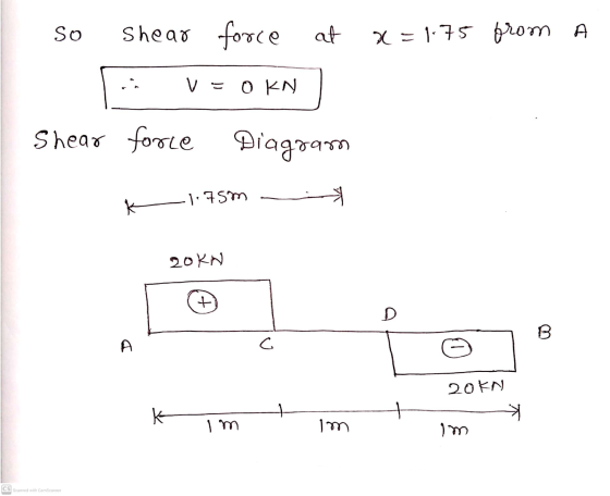
..4953315 Determine the shear force (V) in kN at the point x = 1.75 m from...
3.2.9502460 Determine the shear force (V) in kN at the point x = 3 m from...
 3.2.9502460 Determine the shear force (V) in kN at the point x = 3 m from point A for the beam as loaded in Figure 3.2b6. Given a = 2, b = 2 and w4 = 10. W4 kN/m C B a m b m Figure 3.2b6
6 KM 6 kN/m (3) For the loaded beam determine the shear V and moment M...
 6 KM 6 kN/m (3) For the loaded beam determine the shear V and moment M at a section 200 mm to the right of end A. Ans: V = 0.15 kN, M = 0.15 kN.m 300 mm 300 mm
3. The following beam is exposed to a shear force of V = 30 kN, (20...
 3. The following beam is exposed to a shear force of V = 30 kN, (20 PTS) a) Determine the maximum shear stress developed in the beam. b) The beam has an allowable shear stress of 2.5 MPa. Determine the maximum shear force V that can be applied to the cross section. 150 mm
The internal shear force at a certain section of a steel beam is V=185 kN. The...
 The internal shear force at a certain section of a steel beam is
V=185 kN. The beam cross section shown in the figure has dimensions
of tf=17 mm, bf=300 mm, d=394 mm, and tw=10 mm. Determine:
(a) the shear stress at point A, which is located at
yA=71 mm below the centroid of the wide-flange shape.
(b) the maximum horizontal shear stress in the wide-flange
shape.
The internal shear force at a certain section of a steel beam is V=...
The internal shear force at a certain section of a steel beam is
V=185 kN. The beam cross section shown in the figure has dimensions
of tf=17 mm, bf=300 mm, d=394 mm, and tw=10 mm. Determine:
(a) the shear stress at point A, which is located at
yA=71 mm below the centroid of the wide-flange shape.
(b) the maximum horizontal shear stress in the wide-flange
shape.
The internal shear force at a certain section of a steel beam is V=...
Determine (a) The force in the cable attached at C, and (b) the shear force at...
 Determine (a) The force in the cable attached at C, and (b) the
shear force at point B of the loaded beam shown
Given the following parameters:
P = 475 N
w = 240 N/m
h = 3.5 m
-1.5m-圳 2 m 2 m
Determine (a) The force in the cable attached at C, and (b) the
shear force at point B of the loaded beam shown
Given the following parameters:
P = 475 N
w = 240 N/m
h = 3.5 m
-1.5m-圳 2 m 2 m
2 kN Draw the shear-force and bending-moment diagrams for the beam loaded by the 2-kN force...
 2 kN Draw the shear-force and bending-moment diagrams for the beam loaded by the 2-kN force and the 1.6 kN-m couple. State the value of the bending moment at point B. HW22-2 1.6 kN.m 0.5m 0.5 m 0.5 m
The number of significant digits is set to 3 A positive internal shear force V •...
 The number of significant digits is set to 3
A positive internal shear force V • acts downward on the right-hand face of a beam. • acts upward on the left-hand face of a beam. A positive internal bending moment M • acts counterclockwise on the right-hand face of a beam. • acts clockwise on the left-hand face of a beam. = = Use the graphical method to construct the shear-force and bending-moment diagrams for the beam shown. Label all...
The number of significant digits is set to 3
A positive internal shear force V • acts downward on the right-hand face of a beam. • acts upward on the left-hand face of a beam. A positive internal bending moment M • acts counterclockwise on the right-hand face of a beam. • acts clockwise on the left-hand face of a beam. = = Use the graphical method to construct the shear-force and bending-moment diagrams for the beam shown. Label all...
Question 2: A simply supported beam under loading as shown in Figure 1: 1. Draw the influence lines of the bending moment and shear force at point C (L/4) Using the influence lines to determine t...
 Question 2: A simply supported beam under loading as shown in Figure 1: 1. Draw the influence lines of the bending moment and shear force at point C (L/4) Using the influence lines to determine the bending moment and shear force at section C due to the loading as shown in the figure. 2. 3. There is a distributed live load (w#2.5kN/m) which can vary the location along the beam. Determine the location of the live loads which create the...
Q.3. [20 pts) The figure below shows the shear force diagram for a loaded beam. a-)...
 Q.3. [20 pts) The figure below shows the shear force diagram for a loaded beam. a-) Sketch the beam, showing the loading conditions. b-) Draw the bending moment diagram showing the critical values. V (kN) *** 1.6 2.4 36 16 20 -x (m) 1-24 40
QUESTION 2 For the below loaded truss, P1-20 kN, P2 30 kN, P3-40 kN. 3 m...
 QUESTION 2 For the below loaded truss, P1-20 kN, P2 30 kN, P3-40 kN. 3 m B 12 m--2 m--2 m--2 m--2 m-1-2 m- P Choose the best answer for the force in member KC in kN if the vertical reaction Gy 33.33 kN. State d the member is in tension (T) or compression (C) 12.67 (C) a.67 (C) 6.6 (D 12.67 ( For the below loaded truss, P1-20 kN, P2 30 KN, P3-40 kN. H 3 m D F...
 3.2.9502460 Determine the shear force (V) in kN at the point x = 3 m from point A for the beam as loaded in Figure 3.2b6. Given a = 2, b = 2 and w4 = 10. W4 kN/m C B a m b m Figure 3.2b6
 6 KM 6 kN/m (3) For the loaded beam determine the shear V and moment M at a section 200 mm to the right of end A. Ans: V = 0.15 kN, M = 0.15 kN.m 300 mm 300 mm
 3. The following beam is exposed to a shear force of V = 30 kN, (20 PTS) a) Determine the maximum shear stress developed in the beam. b) The beam has an allowable shear stress of 2.5 MPa. Determine the maximum shear force V that can be applied to the cross section. 150 mm
 The internal shear force at a certain section of a steel beam is
V=185 kN. The beam cross section shown in the figure has dimensions
of tf=17 mm, bf=300 mm, d=394 mm, and tw=10 mm. Determine:
(a) the shear stress at point A, which is located at
yA=71 mm below the centroid of the wide-flange shape.
(b) the maximum horizontal shear stress in the wide-flange
shape.
The internal shear force at a certain section of a steel beam is V=...
The internal shear force at a certain section of a steel beam is
V=185 kN. The beam cross section shown in the figure has dimensions
of tf=17 mm, bf=300 mm, d=394 mm, and tw=10 mm. Determine:
(a) the shear stress at point A, which is located at
yA=71 mm below the centroid of the wide-flange shape.
(b) the maximum horizontal shear stress in the wide-flange
shape.
The internal shear force at a certain section of a steel beam is V=...
 Determine (a) The force in the cable attached at C, and (b) the
shear force at point B of the loaded beam shown
Given the following parameters:
P = 475 N
w = 240 N/m
h = 3.5 m
-1.5m-圳 2 m 2 m
Determine (a) The force in the cable attached at C, and (b) the
shear force at point B of the loaded beam shown
Given the following parameters:
P = 475 N
w = 240 N/m
h = 3.5 m
-1.5m-圳 2 m 2 m
 2 kN Draw the shear-force and bending-moment diagrams for the beam loaded by the 2-kN force and the 1.6 kN-m couple. State the value of the bending moment at point B. HW22-2 1.6 kN.m 0.5m 0.5 m 0.5 m
 The number of significant digits is set to 3
A positive internal shear force V • acts downward on the right-hand face of a beam. • acts upward on the left-hand face of a beam. A positive internal bending moment M • acts counterclockwise on the right-hand face of a beam. • acts clockwise on the left-hand face of a beam. = = Use the graphical method to construct the shear-force and bending-moment diagrams for the beam shown. Label all...
The number of significant digits is set to 3
A positive internal shear force V • acts downward on the right-hand face of a beam. • acts upward on the left-hand face of a beam. A positive internal bending moment M • acts counterclockwise on the right-hand face of a beam. • acts clockwise on the left-hand face of a beam. = = Use the graphical method to construct the shear-force and bending-moment diagrams for the beam shown. Label all...
 Question 2: A simply supported beam under loading as shown in Figure 1: 1. Draw the influence lines of the bending moment and shear force at point C (L/4) Using the influence lines to determine the bending moment and shear force at section C due to the loading as shown in the figure. 2. 3. There is a distributed live load (w#2.5kN/m) which can vary the location along the beam. Determine the location of the live loads which create the...
 Q.3. [20 pts) The figure below shows the shear force diagram for a loaded beam. a-) Sketch the beam, showing the loading conditions. b-) Draw the bending moment diagram showing the critical values. V (kN) *** 1.6 2.4 36 16 20 -x (m) 1-24 40
 QUESTION 2 For the below loaded truss, P1-20 kN, P2 30 kN, P3-40 kN. 3 m B 12 m--2 m--2 m--2 m--2 m-1-2 m- P Choose the best answer for the force in member KC in kN if the vertical reaction Gy 33.33 kN. State d the member is in tension (T) or compression (C) 12.67 (C) a.67 (C) 6.6 (D 12.67 ( For the below loaded truss, P1-20 kN, P2 30 KN, P3-40 kN. H 3 m D F...
Most questions answered within 3 hours.
-
Living in a group could bring several disadvantages to an
individual. What are some of the...
asked 17 seconds ago -
Complete and balance the following reactions. In case of no
reaction occurring write NR.
Mix #1:...
asked 5 minutes ago -
If an economy consumes 75% of any increase in income, then an
increase in autonomous investment...
asked 9 minutes ago -
A shotputter throws the shot with an initial speed of 15.8 m/s
at a 38.0 ∘...
asked 24 minutes ago -
Debra and Merina sell electronic equipment and supplies through
their partnership. They wish to expand their...
asked 25 minutes ago -
How does a linear regression allow you to better estimate
trends, costs, and other factors in...
asked 33 minutes ago -
1. (15%) Describe the difference between a pull (Kanban), push
and CONWIP production systems.
asked 29 minutes ago -
QUESTION 5
The total area under the Z distribution curve is equal to:
a.
10
b....
asked 38 minutes ago -
Using Python
The variables x and y refer to numbers. Write a code segment
that prompts...
asked 53 minutes ago -
If
the coefficient of static friction between a box and the floor is
0.35 with what...
asked 55 minutes ago -
A die is designed to punch holes with a radius of 1.08 10-2 m in
a...
asked 1 hour ago -
government can increase import through
a. export subsidies
b. tax breaks
c. increase import tax
d....
asked 1 hour ago