
Homework Answers

Add Answer to:
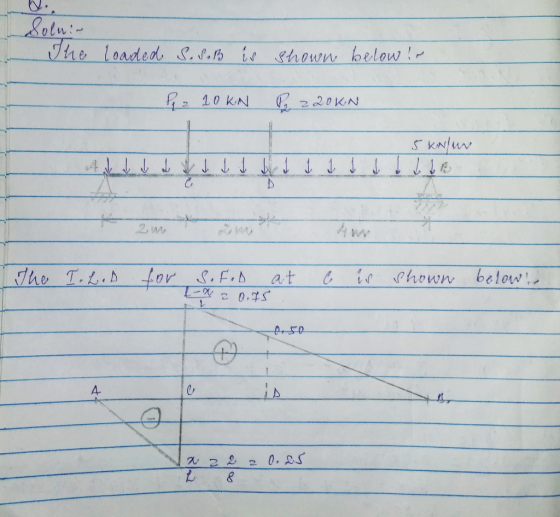
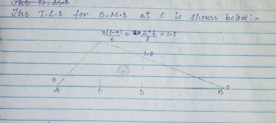
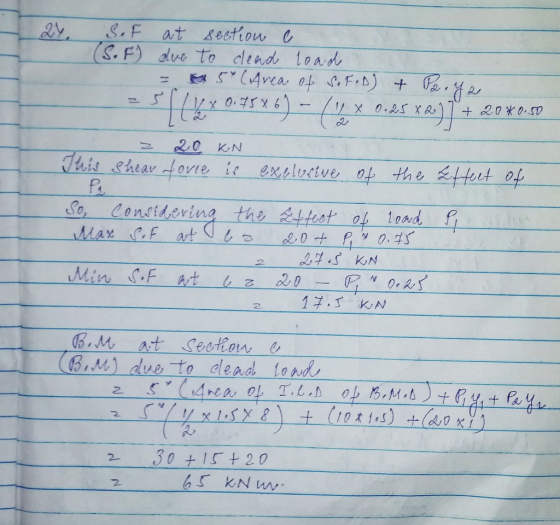
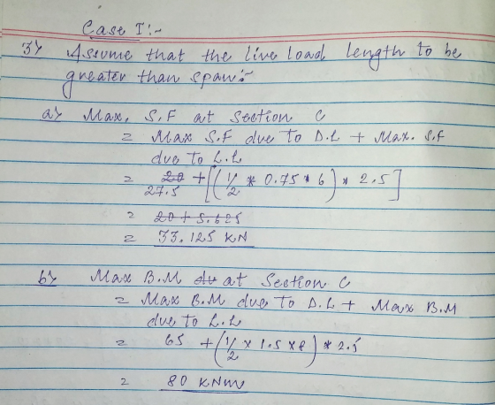
Question 2: A simply supported beam under loading as shown in Figure 1: 1. Draw the influence lines of the bending moment and shear force at point C (L/4) Using the influence lines to determine t...
Shear force and bending moments of the beam. For the simply supported beam subjected to the...
 Shear force and bending moments of the beam.
For the simply supported beam subjected to the loading shown in Figure P7.8 derive equations for the shear force V and the bending moment M for any location in the beam. (Place the origin at point A.) plot the shear-force and bending-moment diagrams for the beam, using the derived functions. report the maximum positive bending moment, the maximum negative bending moment, and their respective locations.
Shear force and bending moments of the beam.
For the simply supported beam subjected to the loading shown in Figure P7.8 derive equations for the shear force V and the bending moment M for any location in the beam. (Place the origin at point A.) plot the shear-force and bending-moment diagrams for the beam, using the derived functions. report the maximum positive bending moment, the maximum negative bending moment, and their respective locations.
QUESTION 1 [15] For the simply supported beam subjected to the loading shown in the figure,...
 QUESTION 1 [15] For the simply supported beam subjected to the loading shown in the figure, a) Derive equations for the shear force V and the bending moment M for any location in the beam. (Place the origin at point A.) b) Report the maximum positive bending moment, the maximum negative bending moment, and their respective locations. 36 KN 180 KN-m X B C D 4 m 5 m 3 m Figure 1
4. For the beam and loading shown, draw the shear force and bending moment diagrams and...
 4. For the beam and loading shown, draw the shear force and bending moment diagrams and determine the maximum bending and shear force and their locations. 20 KN 40 KN B D 250 mm |--2.5 m- 3m-4-2 m 80 mm 5. For the beam and loading shown, draw the shear force and bending moment diagrams and determine the maximum bending and shear force and their locations. 50 KN
Draw the shear force and bending-moment diagrams for the simply supported beam shown. Label each diagram...
 Draw the shear force and bending-moment diagrams for the simply
supported beam shown. Label each diagram with the corresponding
values
1. Draw the shear force and bending-moment diagrams for the simply supported beam shown. Label each diagram with the corresponding values. 3 Pe= 30 KN 4 m - m 3 m - C -40 kN - m
Draw the shear force and bending-moment diagrams for the simply
supported beam shown. Label each diagram with the corresponding
values
1. Draw the shear force and bending-moment diagrams for the simply supported beam shown. Label each diagram with the corresponding values. 3 Pe= 30 KN 4 m - m 3 m - C -40 kN - m
1. For the simply supported beam subjected to the loading shown, Derive equations for the shear...
 1. For the simply supported beam subjected to the loading shown, Derive equations for the shear force V and the bending moment M for any location in the beam. (Place the origin at point A.) a. b. Plot the shear-force and bending-moment diagrams for the beam using the derived functions c. Report the maximum bending moment and its location. 42 kips 6 kips/ft 10 ft 20 ft
a simply supported beam abcd with arectangular cross sectioncarries the loading shown in figure. the...
 a simply supported beam abcd with arectangular cross section
carries the loading shown in figure. the uniform beam has a mass of
33 kg per meter (m kg/m) and a cross section as shown in the
figure. you may take 10 m/s^2 as acceleration.Question A2 A simply supported beam ABCD with a rectangular cross-section carries the loading shown in Figure QA2. The uniform beam has a mass of m kg per meter of length (m kg/m) and a cross-section as shown...
a simply supported beam abcd with arectangular cross section
carries the loading shown in figure. the uniform beam has a mass of
33 kg per meter (m kg/m) and a cross section as shown in the
figure. you may take 10 m/s^2 as acceleration.Question A2 A simply supported beam ABCD with a rectangular cross-section carries the loading shown in Figure QA2. The uniform beam has a mass of m kg per meter of length (m kg/m) and a cross-section as shown...
Draw the shear and bending-moment diagrams for the beam and loading shown.
 Required information Consider the given beam and loading. Draw the shear and bending-moment diagrams for the beam and loading shown.Determine the maximum absolute values of the shear and bending moment. (Round the final answer to one decimal place.) The maximum absolute shear force is _______ KN. The maximum absolute bending moment is _______ kN.m.
For the beam and loading shown, draw the shear and bending moment diagrams, and determine the...
 For the beam and loading shown, draw the shear and bending moment diagrams, and determine the magnitude and location of the maximum shear and bending moment. 2 kN/m AC D 6 NT 3kN/m lm-- 1.2 m 0.6 m
Question 5 10 points Save Answ Draw the shear-force and bending-moment diagrams for the simply supported...
 Question 5 10 points Save Answ Draw the shear-force and bending-moment diagrams for the simply supported beam shown. Determine the bending moment 3.6 m to the right of point A if W = 9.1 kN/m, T = 17.34 kNm, m = 11.9 m, and n = 3.7 m. W T С о В n Question 6 10 points Save Answer Draw the shear-force and bending-moment diagrams for the simply supported beam shown. Determine the shear force 3.3 m to the...
1. Draw influence lines for shear and moment at 15, 25, and 30 feet from the left support for a simply supported be...
 1. Draw influence lines for shear and moment at 15, 25, and 30 feet from the left support for a simply supported beam with a span of 60 feet. Show values of maxima. 2. Using the influence lines in part 1, determine the shear and moment at 15, 25, and 30 feet for a uniformly distributed load of 50 k/ft applied over the length of the beam required to produce the maximum shear and moment at each point. 3. Using...
 Shear force and bending moments of the beam.
For the simply supported beam subjected to the loading shown in Figure P7.8 derive equations for the shear force V and the bending moment M for any location in the beam. (Place the origin at point A.) plot the shear-force and bending-moment diagrams for the beam, using the derived functions. report the maximum positive bending moment, the maximum negative bending moment, and their respective locations.
Shear force and bending moments of the beam.
For the simply supported beam subjected to the loading shown in Figure P7.8 derive equations for the shear force V and the bending moment M for any location in the beam. (Place the origin at point A.) plot the shear-force and bending-moment diagrams for the beam, using the derived functions. report the maximum positive bending moment, the maximum negative bending moment, and their respective locations.
 QUESTION 1 [15] For the simply supported beam subjected to the loading shown in the figure, a) Derive equations for the shear force V and the bending moment M for any location in the beam. (Place the origin at point A.) b) Report the maximum positive bending moment, the maximum negative bending moment, and their respective locations. 36 KN 180 KN-m X B C D 4 m 5 m 3 m Figure 1
 4. For the beam and loading shown, draw the shear force and bending moment diagrams and determine the maximum bending and shear force and their locations. 20 KN 40 KN B D 250 mm |--2.5 m- 3m-4-2 m 80 mm 5. For the beam and loading shown, draw the shear force and bending moment diagrams and determine the maximum bending and shear force and their locations. 50 KN
 Draw the shear force and bending-moment diagrams for the simply
supported beam shown. Label each diagram with the corresponding
values
1. Draw the shear force and bending-moment diagrams for the simply supported beam shown. Label each diagram with the corresponding values. 3 Pe= 30 KN 4 m - m 3 m - C -40 kN - m
Draw the shear force and bending-moment diagrams for the simply
supported beam shown. Label each diagram with the corresponding
values
1. Draw the shear force and bending-moment diagrams for the simply supported beam shown. Label each diagram with the corresponding values. 3 Pe= 30 KN 4 m - m 3 m - C -40 kN - m
 1. For the simply supported beam subjected to the loading shown, Derive equations for the shear force V and the bending moment M for any location in the beam. (Place the origin at point A.) a. b. Plot the shear-force and bending-moment diagrams for the beam using the derived functions c. Report the maximum bending moment and its location. 42 kips 6 kips/ft 10 ft 20 ft
 a simply supported beam abcd with arectangular cross section
carries the loading shown in figure. the uniform beam has a mass of
33 kg per meter (m kg/m) and a cross section as shown in the
figure. you may take 10 m/s^2 as acceleration.Question A2 A simply supported beam ABCD with a rectangular cross-section carries the loading shown in Figure QA2. The uniform beam has a mass of m kg per meter of length (m kg/m) and a cross-section as shown...
a simply supported beam abcd with arectangular cross section
carries the loading shown in figure. the uniform beam has a mass of
33 kg per meter (m kg/m) and a cross section as shown in the
figure. you may take 10 m/s^2 as acceleration.Question A2 A simply supported beam ABCD with a rectangular cross-section carries the loading shown in Figure QA2. The uniform beam has a mass of m kg per meter of length (m kg/m) and a cross-section as shown...
 For the beam and loading shown, draw the shear and bending moment diagrams, and determine the magnitude and location of the maximum shear and bending moment. 2 kN/m AC D 6 NT 3kN/m lm-- 1.2 m 0.6 m
 Question 5 10 points Save Answ Draw the shear-force and bending-moment diagrams for the simply supported beam shown. Determine the bending moment 3.6 m to the right of point A if W = 9.1 kN/m, T = 17.34 kNm, m = 11.9 m, and n = 3.7 m. W T С о В n Question 6 10 points Save Answer Draw the shear-force and bending-moment diagrams for the simply supported beam shown. Determine the shear force 3.3 m to the...
 1. Draw influence lines for shear and moment at 15, 25, and 30 feet from the left support for a simply supported beam with a span of 60 feet. Show values of maxima. 2. Using the influence lines in part 1, determine the shear and moment at 15, 25, and 30 feet for a uniformly distributed load of 50 k/ft applied over the length of the beam required to produce the maximum shear and moment at each point. 3. Using...
Most questions answered within 3 hours.
-
You have a yeast cell culture with a concentration of 5x10^4
cells/ml. If you dilute this...
asked 38 seconds from now -
In which direction the Reaction goes? Show detailed process.
SeO3 + 2ClO2. + 2H3O <---> Se...
asked 12 minutes ago -
Unexposed silver halides are removed from photographic film when
they react with sodium thiosulfate
(Na2S2O3, called...
asked 13 minutes ago -
A 0.3054 gram sample of the mineral chalcopyrite (CuFeS2)
yielded 0.6525 gram BaSO4 precipitate. What is...
asked 13 minutes ago -
An short-seller in Tesla is worried the latest management
earnings forecast is too aggressive and the...
asked 59 minutes ago -
Question 3 (1 point)
Fill in the blank. Speed Car Rental company found that the tire...
asked 59 minutes ago -
1. A copper wire is 26.61 cm long and weighs 1.265 g. The
density of copper...
asked 36 minutes ago -
Remember that a concept sketch consists of a sketch (or
series of sketches), labels, and complete...
asked 39 minutes ago -
on a newly discovered planet, the period of a pendulum with a
length of 2 m...
asked 41 minutes ago -
Why [M(CN)6] is not organometallic even it has metal
to carbon bond too
asked 47 minutes ago -
mstar electric has a bond issue outstanding that has a 20 year
life, a $1,000 par...
asked 55 minutes ago -
This is a Business Writing Question:
Common Types of Faulty Sentence Logic:
A. Mixed constructions
B....
asked 56 minutes ago