
Part A Charging of RC Circuit
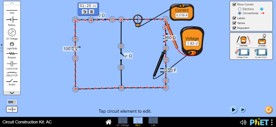
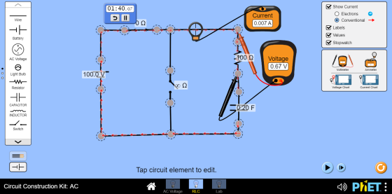
1) Construct a RC circuit (series) with a capacitor, a resistor, a battery, two switches, and appropriate meters that will enable you to make measurements of the parameters for charging up the capacitor. The placement of the switches allows you to measure both charging and discharging of the RC circuit. See diagram below:
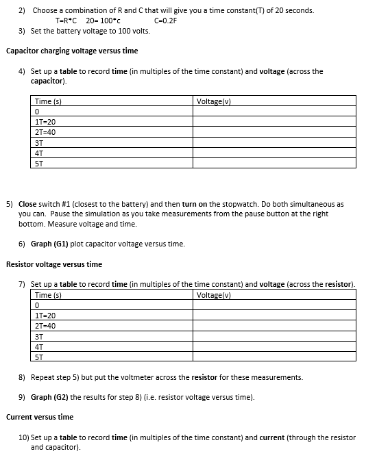
2) Choose a combination of Rand C that will give you a time constant(T) of 20 seconds. T=R*C 20= 100* C=0.2F
3) Set the battery voltage to 100 volts.
Capacitor charging voltage versus time
4) Set up a table to record time (in multiples of the time constant) and voltage (across the capacitor).
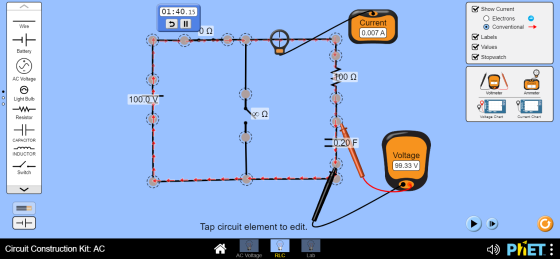
5) Close switch #1 (closest to the battery) and then turn on the stopwatch. Do both simultaneous as you can. Pause the simulation as you take measurements from the pause button at the right bottom. Measure voltage and time.
6) Graph (1) plot capacitor voltage versus time.
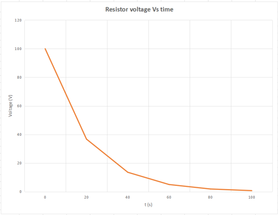
Resistor voltage versus time
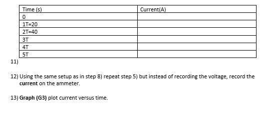
7) Set up a table to record time (in multiples of the time constant) and voltage (across the resistor).
8) Repeat set 5) but put the voltmeter across the resistor for these measurements.
9) Graph (G2) the results for step 8) (i.e. resistor voltage versus time).
Current versus time
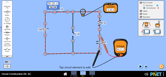
10) Set up a table to record time in multiples of the time constant) and current (through the resistor and capacitor).
12) Using the same setup as in step 8) repeat step 5) but instead of recording the voltage, record the current on the ammeter.
13) Graph (G3) plot current versus time.
Homework Answers
Solution:
Circuit :

(1) Capacitor charging voltage Vs time:
Screenshots:
At t = 0 s :

At t = 20 s :
At t = 40 s :

At t = 60 s :

At t = 80 s :

At t = 100 s :
Data Table:
| Time(s) | Voltage(V) |
| 0 | 0.000 |
| 20 | 64.11 |
| 40 | 86.70 |
| 60 | 95.10 |
| 80 | 98.17 |
| 100 | 99.33 |
Graph (G1):

(2) Resistor voltage Vs time:
Screenshots:
At t = 0 s :

At t = 20 s :

At t = 40 s :
 At t = 60 s
:
At t = 60 s
:
 At t = 80 s :
At t = 100 s :
Data Table:
| Time(s) | Voltage(V) |
| 0 | 100.00 |
| 20 | 36.74 |
| 40 | 13.52 |
| 60 | 4.95 |
| 80 | 1.83 |
| 100 | 0.67 |
Graph(G2) :
(3) Current Vs time:
Screenshot : Same as part(2)
Data Table:
| Time(s) | Current(A) |
| 0 | 1.00 |
| 20 | 0.37 |
| 40 | 0.14 |
| 60 | 0.05 |
| 80 | 0.018 |
| 100 | 0.007 |
Graph(G3) :

Add Answer to:
Construct a RC circuit (series) with a capacitor, a resistor, a battery,
A Series RC circuit consists of a 50V DC source, a 5.0KΩ resistor and a 0.035...
A Series RC circuit consists of a 50V DC source, a 5.0KΩ resistor and a 0.035 μF capacitor. 1) calculate the time constant for the circuit, and 2) calculate the current and voltage drops across the capacitor and the resistor during a charging cycle, employing as time 0,15, and 30 ms.
13. RC circuit A RC circuit has a resistor of 100k and a capacitor of 2004....
 13. RC circuit A RC circuit has a resistor of 100k and a capacitor of 2004. What is the time constant? (5) 2. Figure 3 shows the voltage across a capacitor versus time in a RC-circuit experiment. (5) The applied voltage to the capacitor is V-6. What is the estimated time constant for this capacitor? a) 1-50 b) 50-100s c) 100-150 d) 200-250 e)300-350s Figure 3: Voltage versus time for a capacitor. 3. Working Problem (show all your work!) Figure...
Example 28.12 Charging a Capacitor in an RC Circuit Problem An uncharged capacitor and a resistor...
 Example 28.12 Charging a Capacitor in an RC Circuit Problem An uncharged capacitor and a resistor are battery, as shown in Figure 28.23. If emf = 12.0 V, C = 5.00 AuF, and R = 8.00 x 10⁵ ?, find the time constant of the circuit, the maximum charge on the capacitor, and the charge and current as functions of time. in series to a Figure 28.23 The switch in this series RC circuit, open for times t> , is...
"O OHLEI E PICS! 3. An RC-Circuit is made up of a 12 kO resistor, a...
 "O OHLEI E PICS! 3. An RC-Circuit is made up of a 12 kO resistor, a 40 uF capacitor and a 9.0 V battery. The battery is used to charge the capacitor, and then it is removed from the circuit through the use of a switch, allowing the capacitor to discharge. a. (3 pts.) What is the time constant of the circuit? b. 17 pts.) Calculate the voltage across the capacitor, voltage across the resistor, and the current in the...
PLEASE ANSWER VERY QUICKLY!! I RATE HIGH!! The experiment is on RC circuits and the aim is to determine the time constant. Your group sets up the circuit with a resistor R and a capacitor C conne...
 PLEASE ANSWER VERY QUICKLY!! I RATE HIGH!!
The experiment is on RC circuits and the aim is to determine the time constant. Your group sets up the circuit with a resistor R and a capacitor C connected to a switch and an ideal battery (E). The circuit diagram is shown in the figure. You close the switch at time Os and the voltage across the capacitor Ve and current I in the ammeter are recorded in a spreadsheet using a...
PLEASE ANSWER VERY QUICKLY!! I RATE HIGH!!
The experiment is on RC circuits and the aim is to determine the time constant. Your group sets up the circuit with a resistor R and a capacitor C connected to a switch and an ideal battery (E). The circuit diagram is shown in the figure. You close the switch at time Os and the voltage across the capacitor Ve and current I in the ammeter are recorded in a spreadsheet using a...
A simply RC circuit made up of a capacitor with capacitance C and resistor with resistance...
A simply RC circuit made up of a capacitor with capacitance C and resistor with resistance R = 15 kΩ is attached to a battery with emf E = 24 V. If time constant is 25 µs, what is the capacitance C and the time it takes for the voltage across the capacitor to reach 16 V after the switch is closed at t = 0?
1. A 450 nF capacitor is initially uncharged. The capacitor is connected in series with a...
1. A 450 nF capacitor is initially uncharged. The capacitor is connected in series with a 2,500 resistor and a 6.00 V ideal battery. The circuit is “closed” allowing current to flow and the capacitor to start charging. a. What is the time constant of this RC circuit? b. What is the current through the resistor when the circuit is first “closed”? c. How much time is required for the voltage across the capacitor to reach 5.00 V? d....
Guaranteed thumbs up if all is complete. Thanks in advance! 28. An RC circuit is connected...
 Guaranteed thumbs up if all is complete. Thanks in advance!
28. An RC circuit is connected to a 12.0 V battery at t=0 s and the capacitor voltage is monitored as a function of time. This cap is charging! a) Att = 0.147 s, the capacitor voltage is 20.0% of the battery voltage. What is the RC time constant? b) When will the capacitor be charged to 99.0% of the battery voltage? c) If the cap has value 2.0 mF,...
Guaranteed thumbs up if all is complete. Thanks in advance!
28. An RC circuit is connected to a 12.0 V battery at t=0 s and the capacitor voltage is monitored as a function of time. This cap is charging! a) Att = 0.147 s, the capacitor voltage is 20.0% of the battery voltage. What is the RC time constant? b) When will the capacitor be charged to 99.0% of the battery voltage? c) If the cap has value 2.0 mF,...
This lab involves an animation of an RC circuit. By clicking on the connect battery link...
 This lab involves an animation of an RC circuit. By clicking on
the connect battery link below the animation, you close switch 1
and open switch 2 connecting a 40V battery to the resistor and
capacitor in series. By clicking on the disconnect battery link,
you close switch 2 and open switch 1 eliminating the battery from
the circuit and connecting the resistor and capacitor in series. On
the right hand side a graph of the current vs. time through...
This lab involves an animation of an RC circuit. By clicking on
the connect battery link below the animation, you close switch 1
and open switch 2 connecting a 40V battery to the resistor and
capacitor in series. By clicking on the disconnect battery link,
you close switch 2 and open switch 1 eliminating the battery from
the circuit and connecting the resistor and capacitor in series. On
the right hand side a graph of the current vs. time through...
8. Capacitance in circuits, RC circuits When a voltage source Vo is applied to a capacitor...
 8. Capacitance in circuits, RC circuits When a voltage source Vo is applied to a capacitor in a circuit which has a resistance R, a charge Q CV will build up across the capacitor. This does not happen instantaneously, but takes some time. The charge builds up exponentially with a characteristic time r = RC. Charging: V = v. 1 - e-t/RC) Discharging: Vc = V e-t/RC Page 2 of 3 When t = RC , the exponential is lle,...
 13. RC circuit A RC circuit has a resistor of 100k and a capacitor of 2004. What is the time constant? (5) 2. Figure 3 shows the voltage across a capacitor versus time in a RC-circuit experiment. (5) The applied voltage to the capacitor is V-6. What is the estimated time constant for this capacitor? a) 1-50 b) 50-100s c) 100-150 d) 200-250 e)300-350s Figure 3: Voltage versus time for a capacitor. 3. Working Problem (show all your work!) Figure...
 Example 28.12 Charging a Capacitor in an RC Circuit Problem An uncharged capacitor and a resistor are battery, as shown in Figure 28.23. If emf = 12.0 V, C = 5.00 AuF, and R = 8.00 x 10⁵ ?, find the time constant of the circuit, the maximum charge on the capacitor, and the charge and current as functions of time. in series to a Figure 28.23 The switch in this series RC circuit, open for times t> , is...
 "O OHLEI E PICS! 3. An RC-Circuit is made up of a 12 kO resistor, a 40 uF capacitor and a 9.0 V battery. The battery is used to charge the capacitor, and then it is removed from the circuit through the use of a switch, allowing the capacitor to discharge. a. (3 pts.) What is the time constant of the circuit? b. 17 pts.) Calculate the voltage across the capacitor, voltage across the resistor, and the current in the...
 PLEASE ANSWER VERY QUICKLY!! I RATE HIGH!!
The experiment is on RC circuits and the aim is to determine the time constant. Your group sets up the circuit with a resistor R and a capacitor C connected to a switch and an ideal battery (E). The circuit diagram is shown in the figure. You close the switch at time Os and the voltage across the capacitor Ve and current I in the ammeter are recorded in a spreadsheet using a...
PLEASE ANSWER VERY QUICKLY!! I RATE HIGH!!
The experiment is on RC circuits and the aim is to determine the time constant. Your group sets up the circuit with a resistor R and a capacitor C connected to a switch and an ideal battery (E). The circuit diagram is shown in the figure. You close the switch at time Os and the voltage across the capacitor Ve and current I in the ammeter are recorded in a spreadsheet using a...
 Guaranteed thumbs up if all is complete. Thanks in advance!
28. An RC circuit is connected to a 12.0 V battery at t=0 s and the capacitor voltage is monitored as a function of time. This cap is charging! a) Att = 0.147 s, the capacitor voltage is 20.0% of the battery voltage. What is the RC time constant? b) When will the capacitor be charged to 99.0% of the battery voltage? c) If the cap has value 2.0 mF,...
Guaranteed thumbs up if all is complete. Thanks in advance!
28. An RC circuit is connected to a 12.0 V battery at t=0 s and the capacitor voltage is monitored as a function of time. This cap is charging! a) Att = 0.147 s, the capacitor voltage is 20.0% of the battery voltage. What is the RC time constant? b) When will the capacitor be charged to 99.0% of the battery voltage? c) If the cap has value 2.0 mF,...
 This lab involves an animation of an RC circuit. By clicking on
the connect battery link below the animation, you close switch 1
and open switch 2 connecting a 40V battery to the resistor and
capacitor in series. By clicking on the disconnect battery link,
you close switch 2 and open switch 1 eliminating the battery from
the circuit and connecting the resistor and capacitor in series. On
the right hand side a graph of the current vs. time through...
This lab involves an animation of an RC circuit. By clicking on
the connect battery link below the animation, you close switch 1
and open switch 2 connecting a 40V battery to the resistor and
capacitor in series. By clicking on the disconnect battery link,
you close switch 2 and open switch 1 eliminating the battery from
the circuit and connecting the resistor and capacitor in series. On
the right hand side a graph of the current vs. time through...
 8. Capacitance in circuits, RC circuits When a voltage source Vo is applied to a capacitor in a circuit which has a resistance R, a charge Q CV will build up across the capacitor. This does not happen instantaneously, but takes some time. The charge builds up exponentially with a characteristic time r = RC. Charging: V = v. 1 - e-t/RC) Discharging: Vc = V e-t/RC Page 2 of 3 When t = RC , the exponential is lle,...
Most questions answered within 3 hours.
-
A student takes a multiple-choice test that has 10 questions.
Each question has two choices. The...
asked 18 minutes ago -
Willie Keeler has a lifetime batting average of 0.341. Assume
that Willie Keeler came to bat...
asked 19 minutes ago -
Which of the following has the highest boiling point?
A) 0.5m NaCl
B) 0.5m C6H12O6
C)...
asked 39 minutes ago -
12. A firm is producing at an output level where
AR = MC > AC >...
asked 35 minutes ago -
Radovilsky Manufacturing Company, in Hayward, California,
makes flashing lights for toys. The company operates its production...
asked 38 minutes ago -
As an athlete exercises, sweat is produced and evaporated to
jelp maintain a proper body temperature....
asked 37 minutes ago -
Which of these macromolecules is most prevalent (by mass) in the
environment? What particular challenge does...
asked 39 minutes ago -
Consider two stocks. Stock A has a standard deviation of 46% and
stock B has a...
asked 43 minutes ago -
Give a unary language (using only input alphabet ∑={1} )that is
not Turing- recognizable and prove...
asked 54 minutes ago -
1. Write the balanced net reaction for a Ti (s) | TiCl2 (aq) ||
InCl3 (aq)...
asked 51 minutes ago -
3) Answer the following questions:please respond in one
paragraph
In your opinion, what are the crucial...
asked 58 minutes ago -
Assume that the readings at freezing on a batch of thermometers
are normally distributed with a...
asked 1 hour ago