
Homework Answers


Add Answer to:
Problem 12.34 Consider the frame shown in (Figure 1). The axial stress in a column is...
Problem 10.19 Consider the frame shown in (Figure 1). Assume the support at A is fixed...
 Problem 10.19 Consider the frame shown in (Figure 1). Assume the support at A is fixed and C is a pin. EI is constant. Part A Determine the internal end moment MBA acting on member AB of the frame at B measured clockwise. Express your answer using three significant figures. Enter positive value if the moment is clockwise and negative value if the moment is counterclockwise. MBA = 40.8 k ft Submit Previous Answers Correct Part B Determine the internal...
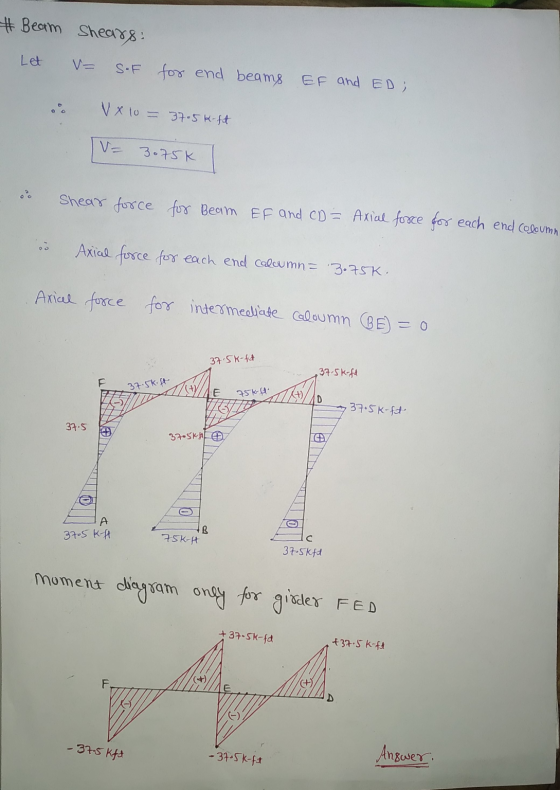
Problem 12.34 Consider the frame shown in (Figure 1). Part B Use the portal method of...
 Problem 12.34 Consider the frame shown in (Figure 1). Part B Use the portal method of analysis and draw the moment diagram for girder FED Click on "add vertical line off to add discontinuity lines. Then click on "add segment" button to add functions between the lines. Note 1 - Make sure you place only one vertical line at places that require a vertical line. If you inadvertently place two vertical lines at the same place, it will appear overlap,...
Consider the building frame shown in (Figure 1). Use the cantilever method of analysis. Each column...
 Consider the building frame shown in (Figure 1). Use the cantilever method of analysis. Each column has the cross-sectional area indicated. II Review Draw the moment diagram for girder IJKL. Follow the sign convention. Click on "add vertical line off" to add discontinuity lines. Then click on "add segment" button to add functions between the lines. Note 1 - You should not draw an "extra" discontinuity line at the point where the graph passes the x-axis. Note 2 - Be...
Problem 10.22 Consider the frame shown in (Figure 1). Assume the supports at A and B...
 Problem 10.22 Consider the frame shown in (Figure 1). Assume the supports at A and B are foxed. Er is constant Click on 'add vertical line off to add discontinuity lines. Then click on "add segment" button to add functions betwe lines, Note 1. Make sure you place only one vertical line at places that require a vertical line. If you inadvertently place two lines at the same place, it will appear correct visually because the lines overlap, but the...
All i need is graphs thank you! Problem 9.22 Consider the frame shown in (Figure 1)....
 All i need is graphs thank you!
Problem 9.22 Consider the frame shown in (Figure 1). Assume A and B are pins and the joint at C is fixed connected. Er is constant. Draw the moment diagram for member AC. Follow the sign convention for the internal loadings in the beam shown in the figure below. Click on "add vertical line off" to add discontinuity lines. Then click on "add segment" button to add functions between the lines. Note 1...
All i need is graphs thank you!
Problem 9.22 Consider the frame shown in (Figure 1). Assume A and B are pins and the joint at C is fixed connected. Er is constant. Draw the moment diagram for member AC. Follow the sign convention for the internal loadings in the beam shown in the figure below. Click on "add vertical line off" to add discontinuity lines. Then click on "add segment" button to add functions between the lines. Note 1...
Consider the truss shown in (Figure 1). Follow the sign convention. Draw the influence line for...
 Consider the truss shown in (Figure 1). Follow the sign convention. Draw the influence line for the force in member CJ. Indicate the values of the influence line at each joint along the bottom cord of the truss and indicate the points where the influence line passes the z-axis. Click on "add vertical line off" to add discontinuity lines. Then click on "add segment" button to add functions between the lines. Note 1 - Draw discontinuity lines at each joint...
Problem 4.59 Review Des the moment diagrams for the bean shown in Figure 1) using the...
 Problem 4.59 Review Des the moment diagrams for the bean shown in Figure 1) using the method of superposition. Consider the beam to be catevered from the support at B. Follow the sign convention Part A Draw the moment diagram for the force worted by the pin Click on vertical line off to add vertical lines. The condiment" button to functions between the lines Note 1. Make sure you place only one vertical line at places that require a vertical...
1 Review - Part B Draw the moment diagrams for the beam shown in (Figure 1)...
 1 Review - Part B Draw the moment diagrams for the beam shown in (Figure 1) using the method of superposition. Consider the beam to be cantilevered from the support at (BV). Follow the sign convention. Draw the moment diagram for the force shown in the figure below. Click on "add vertical line off" to add vertical lines. Then click on "add segment" button to add functions between the lines. Note 1 - Make sure you place only one vertical...
u Reviev Consider the beam shown in (Figure 1). El is constant. Part F Draw the...
 u Reviev Consider the beam shown in (Figure 1). El is constant. Part F Draw the moment diagram for the beam. Follow the sign convention. Click on "add vertical line off" to add discontinuity lines. Then click on "add segment" button to add functions between the lines. Note 1 - Make sure you place only one vertical line at places that require a vertical line. If you inadvertently place two vertical lines at the same place, it will appear correct...
Part A Draw the shear diagram for the beam. Follow the sign convention. (Figure 1) Click...
 Part A
Draw the shear diagram for the beam. Follow the sign convention.
(Figure 1)
Click on "add vertical line off" to add discontinuity lines.
Then click on "add segment" button to add functions between the
lines.
Note 1 - You should not draw an "extra" discontinuity line at the
point where the curve passes the x-axis.
Note 2 - Be sure to indicate the correct types of the functions
between the lines, e.g. if in your answer the type...
Part A
Draw the shear diagram for the beam. Follow the sign convention.
(Figure 1)
Click on "add vertical line off" to add discontinuity lines.
Then click on "add segment" button to add functions between the
lines.
Note 1 - You should not draw an "extra" discontinuity line at the
point where the curve passes the x-axis.
Note 2 - Be sure to indicate the correct types of the functions
between the lines, e.g. if in your answer the type...
 Problem 10.19 Consider the frame shown in (Figure 1). Assume the support at A is fixed and C is a pin. EI is constant. Part A Determine the internal end moment MBA acting on member AB of the frame at B measured clockwise. Express your answer using three significant figures. Enter positive value if the moment is clockwise and negative value if the moment is counterclockwise. MBA = 40.8 k ft Submit Previous Answers Correct Part B Determine the internal...
 Problem 12.34 Consider the frame shown in (Figure 1). Part B Use the portal method of analysis and draw the moment diagram for girder FED Click on "add vertical line off to add discontinuity lines. Then click on "add segment" button to add functions between the lines. Note 1 - Make sure you place only one vertical line at places that require a vertical line. If you inadvertently place two vertical lines at the same place, it will appear overlap,...
 Consider the building frame shown in (Figure 1). Use the cantilever method of analysis. Each column has the cross-sectional area indicated. II Review Draw the moment diagram for girder IJKL. Follow the sign convention. Click on "add vertical line off" to add discontinuity lines. Then click on "add segment" button to add functions between the lines. Note 1 - You should not draw an "extra" discontinuity line at the point where the graph passes the x-axis. Note 2 - Be...
 Problem 10.22 Consider the frame shown in (Figure 1). Assume the supports at A and B are foxed. Er is constant Click on 'add vertical line off to add discontinuity lines. Then click on "add segment" button to add functions betwe lines, Note 1. Make sure you place only one vertical line at places that require a vertical line. If you inadvertently place two lines at the same place, it will appear correct visually because the lines overlap, but the...
 All i need is graphs thank you!
Problem 9.22 Consider the frame shown in (Figure 1). Assume A and B are pins and the joint at C is fixed connected. Er is constant. Draw the moment diagram for member AC. Follow the sign convention for the internal loadings in the beam shown in the figure below. Click on "add vertical line off" to add discontinuity lines. Then click on "add segment" button to add functions between the lines. Note 1...
All i need is graphs thank you!
Problem 9.22 Consider the frame shown in (Figure 1). Assume A and B are pins and the joint at C is fixed connected. Er is constant. Draw the moment diagram for member AC. Follow the sign convention for the internal loadings in the beam shown in the figure below. Click on "add vertical line off" to add discontinuity lines. Then click on "add segment" button to add functions between the lines. Note 1...
 Consider the truss shown in (Figure 1). Follow the sign convention. Draw the influence line for the force in member CJ. Indicate the values of the influence line at each joint along the bottom cord of the truss and indicate the points where the influence line passes the z-axis. Click on "add vertical line off" to add discontinuity lines. Then click on "add segment" button to add functions between the lines. Note 1 - Draw discontinuity lines at each joint...
 Problem 4.59 Review Des the moment diagrams for the bean shown in Figure 1) using the method of superposition. Consider the beam to be catevered from the support at B. Follow the sign convention Part A Draw the moment diagram for the force worted by the pin Click on vertical line off to add vertical lines. The condiment" button to functions between the lines Note 1. Make sure you place only one vertical line at places that require a vertical...
 1 Review - Part B Draw the moment diagrams for the beam shown in (Figure 1) using the method of superposition. Consider the beam to be cantilevered from the support at (BV). Follow the sign convention. Draw the moment diagram for the force shown in the figure below. Click on "add vertical line off" to add vertical lines. Then click on "add segment" button to add functions between the lines. Note 1 - Make sure you place only one vertical...
 u Reviev Consider the beam shown in (Figure 1). El is constant. Part F Draw the moment diagram for the beam. Follow the sign convention. Click on "add vertical line off" to add discontinuity lines. Then click on "add segment" button to add functions between the lines. Note 1 - Make sure you place only one vertical line at places that require a vertical line. If you inadvertently place two vertical lines at the same place, it will appear correct...
 Part A
Draw the shear diagram for the beam. Follow the sign convention.
(Figure 1)
Click on "add vertical line off" to add discontinuity lines.
Then click on "add segment" button to add functions between the
lines.
Note 1 - You should not draw an "extra" discontinuity line at the
point where the curve passes the x-axis.
Note 2 - Be sure to indicate the correct types of the functions
between the lines, e.g. if in your answer the type...
Part A
Draw the shear diagram for the beam. Follow the sign convention.
(Figure 1)
Click on "add vertical line off" to add discontinuity lines.
Then click on "add segment" button to add functions between the
lines.
Note 1 - You should not draw an "extra" discontinuity line at the
point where the curve passes the x-axis.
Note 2 - Be sure to indicate the correct types of the functions
between the lines, e.g. if in your answer the type...
Most questions answered within 3 hours.
-
(Expected rate of return and risk) Carter Inc. is evaluating a
security. Calculate the investment’s expected...
asked 28 minutes ago -
What specific indicators can point to lack of progress for
African Americans in American society?
asked 1 hour ago -
1-The Electrons in a beam are moving at 2.7×10⁸ m/s in an
electric field of 15000...
asked 1 hour ago -
A gas tank is a vertical cylinder. It has a radius of 1m, a
height of...
asked 2 hours ago -
Accent Software faces the following conditions. All of these
support Accent’s use of a market-penetration pricing...
asked 3 hours ago -
A mathematically inclined friend emails you the following
instructions: "Meet me in the cafeteria the first...
asked 3 hours ago -
A monopoly sells in two countries . The demand curves in the two
countries are p1...
asked 4 hours ago -
A .15kg rubber ball is bounced off a wall. Before hitting the
wall, the ball moves...
asked 4 hours ago -
A manufacturing company preparing to build a new plant is
considering three potential locations for it....
asked 4 hours ago -
B. If compound Y has approximately the same values of solubility
in toluene as compound X,...
asked 5 hours ago -
Oscar Inc. has inventory in Japan valued at 39,051,000 Yen one
year ago. One year ago...
asked 5 hours ago -
If Canada suffered from "fundamental disequilibrium," and its
government choose not to devalue its currency, a...
asked 5 hours ago