
Homework Answers


Add Answer to:
Question 2 Figure 2 represents block diagram and signal flow chart which are commonly used in...
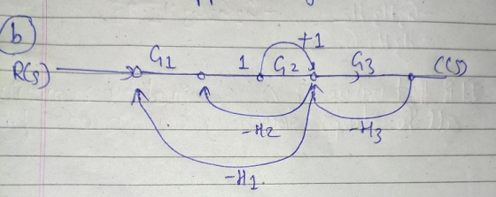
Consider the block diagram in figure 2 a. Hy R(s) GI G G3 +1 Figure 2 Convert figure 2 to signal flow graph. Using your...
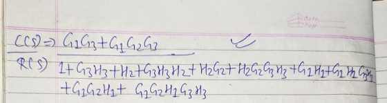
 Consider the block diagram in figure 2 a. Hy R(s) GI G G3 +1 Figure 2 Convert figure 2 to signal flow graph. Using your result in Q5ali), determine the transfer function using the Mason's gain (2marks) formula.
Consider the block diagram in figure 2 a. Hy R(s) GI G G3 +1 Figure 2 Convert figure 2 to signal flow graph. Using your result in Q5ali), determine the transfer function using the Mason's gain (2marks) formula.
Consider the block diagram in figure 2 a. Hy R(s) GI G G3 +1 Figure 2 Convert figure 2 to signal flow graph. Using your result in Q5ali), determine the transfer function using the Mason's gain (2marks) formula.
Draw a signal flow graph from the given block diagram below and find a transfer function...
 Draw a signal flow graph from the given block diagram below and find a transfer function Ys X() using Mason's rule. (15 pts)Bke i G3 (s) x(s) G2 (s) - Y(s) → H1 (s) C. H2 (s) 63
Question 1: Given the Block Diagram as shown in Figure 1. Draw the Signal Flow Graph...
 Question 1: Given the Block Diagram as shown in Figure 1. Draw the Signal Flow Graph and find the overall system Transfer Function using Mason's Gain formula. R G G Gg H G Figure 1. Block Diagram Representation
4)Convert the following block diagram into signal flow graph (15 marks) R(s) X (s) U(s) H.(s)...
 4)Convert the following block diagram into signal flow graph (15 marks) R(s) X (s) U(s) H.(s) D(s) G(s) Xx(s) Hz(s) 5) Using Mason's gain formula, find the transfer function of the following systems (40 marks).
2. Determine the closed-loop transfer function Y (using Signal Flow Graphs or Block U(s) Diagram Transformations)...
 2. Determine the closed-loop transfer function Y (using Signal Flow Graphs or Block U(s) Diagram Transformations) for the system shown in Figure 2 U(s) Y (s) 0 do
Question 3 a) Reduce the block diagram in Figure 3 to a single block with the...
 Question 3 a) Reduce the block diagram in Figure 3 to a single block with the overall tra (10 marks) function. H2(s) Figure 3: A block diagram comprising multiple subsystems and controllers b) For the system in Figure 4, assume that the plant has the following transfer function: If the controller in Figure 4 is proportional-only, determine the following: (2 marks) i) The system type. i) The steady-state error, es, if the reference signal, R(s) is a unit step input....
Use Mason's rule to find the transfer function of the signal-flow diagram shown in Figure below....
 Use Mason's rule to find the transfer function of the signal-flow diagram shown in Figure below. Knowing that: G1=7 G2=1/s G3=2 G4=1/s G5=-5 G6=1/s G7=-4 G8=5 G9=2 G10=9 G11=6 G12=3 H1=-4 H2=-2 H3=2 H4=-3 H5=-6 H6=1 G9 G10 G8 G11 R(s) G: G2 G3 G4 G5 G6 Y(s) 5 HI H2 H3 Ha Hs G12 HG
Q2. (a)Figure Q2(a) shows the block diagram of a system network. Determine the (7 marks) closed-loop...
 Q2. (a)Figure Q2(a) shows the block diagram of a system network. Determine the (7 marks) closed-loop transfer function T(s) C(s)/R(s). Cts) Ris) + Figure Q2(a)
Consider the system described in the figure below. a. Draw a signal-flow diagram for the given...
 Consider the system described in the figure below. a. Draw a signal-flow diagram for the given system. b. Using Mason's rule find the transfer function of the system. c. Find the value(s) of K for which the system will be stable. R(S) C(s) 5+1
Consider the system described in the figure below. a. Draw a signal-flow diagram for the given...
 Consider the system described in the figure below. a. Draw a signal-flow diagram for the given system. b. Using Mason's rule find the transfer function of the system. c. Find the value(s) of K for which the system will be stable. R(S) C(s) WIN 1 5+1
 Consider the block diagram in figure 2 a. Hy R(s) GI G G3 +1 Figure 2 Convert figure 2 to signal flow graph. Using your result in Q5ali), determine the transfer function using the Mason's gain (2marks) formula.
Consider the block diagram in figure 2 a. Hy R(s) GI G G3 +1 Figure 2 Convert figure 2 to signal flow graph. Using your result in Q5ali), determine the transfer function using the Mason's gain (2marks) formula.
Consider the block diagram in figure 2 a. Hy R(s) GI G G3 +1 Figure 2 Convert figure 2 to signal flow graph. Using your result in Q5ali), determine the transfer function using the Mason's gain (2marks) formula.
 Draw a signal flow graph from the given block diagram below and find a transfer function Ys X() using Mason's rule. (15 pts)Bke i G3 (s) x(s) G2 (s) - Y(s) → H1 (s) C. H2 (s) 63
 Question 1: Given the Block Diagram as shown in Figure 1. Draw the Signal Flow Graph and find the overall system Transfer Function using Mason's Gain formula. R G G Gg H G Figure 1. Block Diagram Representation
 4)Convert the following block diagram into signal flow graph (15 marks) R(s) X (s) U(s) H.(s) D(s) G(s) Xx(s) Hz(s) 5) Using Mason's gain formula, find the transfer function of the following systems (40 marks).
 2. Determine the closed-loop transfer function Y (using Signal Flow Graphs or Block U(s) Diagram Transformations) for the system shown in Figure 2 U(s) Y (s) 0 do
 Question 3 a) Reduce the block diagram in Figure 3 to a single block with the overall tra (10 marks) function. H2(s) Figure 3: A block diagram comprising multiple subsystems and controllers b) For the system in Figure 4, assume that the plant has the following transfer function: If the controller in Figure 4 is proportional-only, determine the following: (2 marks) i) The system type. i) The steady-state error, es, if the reference signal, R(s) is a unit step input....
 Use Mason's rule to find the transfer function of the signal-flow diagram shown in Figure below. Knowing that: G1=7 G2=1/s G3=2 G4=1/s G5=-5 G6=1/s G7=-4 G8=5 G9=2 G10=9 G11=6 G12=3 H1=-4 H2=-2 H3=2 H4=-3 H5=-6 H6=1 G9 G10 G8 G11 R(s) G: G2 G3 G4 G5 G6 Y(s) 5 HI H2 H3 Ha Hs G12 HG
 Q2. (a)Figure Q2(a) shows the block diagram of a system network. Determine the (7 marks) closed-loop transfer function T(s) C(s)/R(s). Cts) Ris) + Figure Q2(a)
 Consider the system described in the figure below. a. Draw a signal-flow diagram for the given system. b. Using Mason's rule find the transfer function of the system. c. Find the value(s) of K for which the system will be stable. R(S) C(s) 5+1
 Consider the system described in the figure below. a. Draw a signal-flow diagram for the given system. b. Using Mason's rule find the transfer function of the system. c. Find the value(s) of K for which the system will be stable. R(S) C(s) WIN 1 5+1
Most questions answered within 3 hours.
-
What do the phenomena of overshadowing, the CS preexposure
effect, and relative validity of cues have...
asked 20 minutes ago -
Assuming air has a density of 1.17 g/L and .973 atm what is the
average molar...
asked 13 minutes ago -
A student studying for a vocabulary test knows the meanings of
16 words from a list...
asked 8 minutes ago -
Developmental Biology! Please answer all the questions
7) Mislocalization of oscar to the side of the...
asked 7 minutes ago -
We have two Earths, one as ours and another that is twice
heavier than that of...
asked 15 minutes ago -
At an annual interest rate of 6%, which would you prefer; three
annual year-end cash flows...
asked 14 minutes ago -
1. (40’) In myStack.cpp, implement the member functions of the
class myStack, which is the class...
asked 15 minutes ago -
MnO4^- + C2O4^2- ---->MnO2 +CO3^2- balance in basic media
asked 33 minutes ago -
What is the missing keyword in the program below?
public class Batman {
public static int...
asked 30 minutes ago -
The Southern Oscillation can be best described
as
relative changes between two pressure systems.
variation in...
asked 31 minutes ago -
We predict that learning statistics will increase a student's
IQ. Those not learning statistics have a...
asked 37 minutes ago -
Write a procedure of how you would separate benzoic acid
(acidic), decane (neutral), and adenine (basic)...
asked 37 minutes ago