Note :-
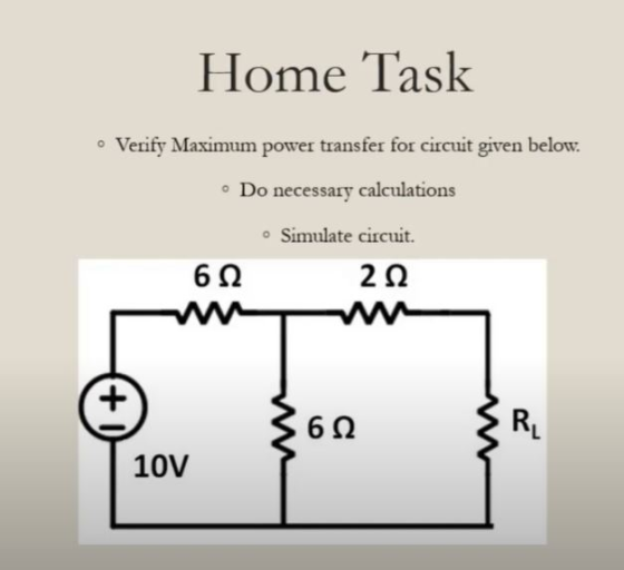
1. Need Proper Calculations with relevant Explanation.
2. Simulation wil be Done on " FALSTAD".( falstad.com/circuit/circuitjs.html )
3. Your "Simulated" and "Calculated" values Should Same.
Homework Answers


Add Answer to:
Note :-
1. Need Proper Calculations with relevant Explanation.
2. Simulation wil be Done on "...
***JUST NEED THE LEDGER DONE # 2 *** ***JUST NEED THE LEDGER DONE # 2 ***...
 ***JUST NEED THE LEDGER DONE # 2 ***
***JUST NEED THE LEDGER DONE # 2 ***
INSTRUCTIONS AND TRANSACTIONS FOR THE CHAPTER 3 "BIG" PROJECT WORTH 100 POINTS NOTE: YOU MUST USE THE PROJECT WORKPAPERS (EXCEL FILE) PROVIDED IN D2L CONTENT / CHAPTER 3 FOLDER. NO OTHER FILES WILL BE ACCEPTED. On January 1, 2019, Bruce Wayne created a new Crime Watch agency called Batman's Watchdog Service. The following transactions occurred during...
***JUST NEED THE LEDGER DONE # 2 ***
***JUST NEED THE LEDGER DONE # 2 ***
***JUST NEED THE LEDGER DONE # 2 ***
INSTRUCTIONS AND TRANSACTIONS FOR THE CHAPTER 3 "BIG" PROJECT WORTH 100 POINTS NOTE: YOU MUST USE THE PROJECT WORKPAPERS (EXCEL FILE) PROVIDED IN D2L CONTENT / CHAPTER 3 FOLDER. NO OTHER FILES WILL BE ACCEPTED. On January 1, 2019, Bruce Wayne created a new Crime Watch agency called Batman's Watchdog Service. The following transactions occurred during...
MENG 207-ELECTRICITY Department of Engineering & Design at Eastern Washington University Lab 6 PRE LAB 1. Print out lab handout and bring to lalb 2. Do calculations for part 1 in RC CIRCUIT s...
 MENG 207-ELECTRICITY Department of Engineering & Design at Eastern Washington University Lab 6 PRE LAB 1. Print out lab handout and bring to lalb 2. Do calculations for part 1 in RC CIRCUIT section. 3. Do calculations for part 1 in RL CIRCUIT section. 4. Do calculations for part 1 in RLC CIRCUIT section OBECTVE:response Use Multisim to study the transient response of an RC and RL circuit, and the frequency response of an RLC circuit. PROCEDURES 1. Record every...
Lab Procedure: Part 1: Source Free RC Circuit V(t) ilts C3 (R3 21ko 1uF IC=10V a)...
 Lab Procedure: Part 1: Source Free RC Circuit V(t) ilts C3 (R3 21ko 1uF IC=10V a) For the circuit shown above, provide the equation and calculate the following: 1. The source free equation for V(t) for V(O)= 10 volts 2. The equation for it) 3. V(t) and i(t) for t = t (one time constant) b) Now, enter the circuit using Multisim Schematic Capture. c) Simulate using Transient mode with a graphical output and verify graphical results with your calculations....
Lab - 4.pdf (page 1 of 2) @ Search R2 Prelab Resistor Selection R1 w a....
 Lab - 4.pdf (page 1 of 2) @ Search R2 Prelab Resistor Selection R1 w a. A circuit based on the configuration in Figure 1 1 ΚΩ needs to produce: V2 R3 V1 1) A leftward current of 3.9 mA in R5. V3 2) A top-positive voltage of 1.5 V across R4. 3) A power of 2.4 mW in RL. 4.0V R4 RL = 5602 b. Sketch Figure 1 on a blank sheet of paper, add notations as needed, and...
2- Set the two independent power sources to Vsi 6V and Veo" 10 V and measure...
 2- Set the two independent power sources to Vsi 6V and Veo" 10 V and measure their actual values using the DMM. Actual Values of power sources: 4.47 VS15.99 Vs- 3- Using the breadboard construct the circuit shown in Figure 4,1 (repeated below for convenience). Use the resistors measured in Step 1 (above) and the power sources Vsi- 6 V, and Vs2 -10 V. IR3 IRI RS. R5 R1 R3 Va V4 V2 V1 ww ww It 12 R4 R23...
Introduction The purpose of this project is to design, simulate, analyze, implement, and test a single-supply,...
Introduction The purpose of this project is to design, simulate, analyze, implement, and test a single-supply, multistage, transistor amplifier which fulfills a set of specifications. For this project, the pre-lab shall be treated as your formal design report and therefore must be much more detailed than usual (please see Evaluation heading on the next page of this document). The report shall be submitted to the TA by the deadline. The report is an individual assignment. Specifications • Power supply: +???...
Problem 3: Design Problem On Figure P3a, you have a Common Source (CS) n-channel MOSFET amplifier....
 Problem 3: Design Problem On Figure P3a, you have a Common Source (CS) n-channel MOSFET amplifier. Notice the absence of a source resistor Rsig and load resistor R. If we know how the present amplifier (the one on Figure P3a) behaves without Rsig and RL, we can infer its behaviors if Rsig and R were to be added. design the amplifier circuit on Figure P3a, i.e., you have to find appropriate values for RGj You are to RG,, RD, and...
summarizr the followung info and write them in your own words and break them into different...
summarizr the followung info and write them in your own words and break them into different key points. 6.5 Metering Chamber: 6.5.1 The minimum size of the metering box is governed by the metering area required to obtain a representative test area for the specimen (see 7.2) and for maintenance of reasonable test accuracy. For example, for specimens incorporating air spaces or stud spaces, the metering area shall span an integral number of spaces (see 5.5). The depth of...
summatize the following info and break them into differeng key points. write them in yojr own...
 summatize the following info and break them into differeng key points. write them in yojr own words
apartus
6.1 Introduction—The design of a successful hot box appa- ratus is influenced by many factors. Before beginning the design of an apparatus meeting this standard, the designer shall review the discussion on the limitations and accuracy, Section 13, discussions of the energy flows in a hot box, Annex A2, the metering box wall loss flow, Annex A3, and flanking loss, Annex...
summatize the following info and break them into differeng key points. write them in yojr own words
apartus
6.1 Introduction—The design of a successful hot box appa- ratus is influenced by many factors. Before beginning the design of an apparatus meeting this standard, the designer shall review the discussion on the limitations and accuracy, Section 13, discussions of the energy flows in a hot box, Annex A2, the metering box wall loss flow, Annex A3, and flanking loss, Annex...
 ***JUST NEED THE LEDGER DONE # 2 ***
***JUST NEED THE LEDGER DONE # 2 ***
INSTRUCTIONS AND TRANSACTIONS FOR THE CHAPTER 3 "BIG" PROJECT WORTH 100 POINTS NOTE: YOU MUST USE THE PROJECT WORKPAPERS (EXCEL FILE) PROVIDED IN D2L CONTENT / CHAPTER 3 FOLDER. NO OTHER FILES WILL BE ACCEPTED. On January 1, 2019, Bruce Wayne created a new Crime Watch agency called Batman's Watchdog Service. The following transactions occurred during...
***JUST NEED THE LEDGER DONE # 2 ***
***JUST NEED THE LEDGER DONE # 2 ***
***JUST NEED THE LEDGER DONE # 2 ***
INSTRUCTIONS AND TRANSACTIONS FOR THE CHAPTER 3 "BIG" PROJECT WORTH 100 POINTS NOTE: YOU MUST USE THE PROJECT WORKPAPERS (EXCEL FILE) PROVIDED IN D2L CONTENT / CHAPTER 3 FOLDER. NO OTHER FILES WILL BE ACCEPTED. On January 1, 2019, Bruce Wayne created a new Crime Watch agency called Batman's Watchdog Service. The following transactions occurred during...
 MENG 207-ELECTRICITY Department of Engineering & Design at Eastern Washington University Lab 6 PRE LAB 1. Print out lab handout and bring to lalb 2. Do calculations for part 1 in RC CIRCUIT section. 3. Do calculations for part 1 in RL CIRCUIT section. 4. Do calculations for part 1 in RLC CIRCUIT section OBECTVE:response Use Multisim to study the transient response of an RC and RL circuit, and the frequency response of an RLC circuit. PROCEDURES 1. Record every...
 Lab Procedure: Part 1: Source Free RC Circuit V(t) ilts C3 (R3 21ko 1uF IC=10V a) For the circuit shown above, provide the equation and calculate the following: 1. The source free equation for V(t) for V(O)= 10 volts 2. The equation for it) 3. V(t) and i(t) for t = t (one time constant) b) Now, enter the circuit using Multisim Schematic Capture. c) Simulate using Transient mode with a graphical output and verify graphical results with your calculations....
 Lab - 4.pdf (page 1 of 2) @ Search R2 Prelab Resistor Selection R1 w a. A circuit based on the configuration in Figure 1 1 ΚΩ needs to produce: V2 R3 V1 1) A leftward current of 3.9 mA in R5. V3 2) A top-positive voltage of 1.5 V across R4. 3) A power of 2.4 mW in RL. 4.0V R4 RL = 5602 b. Sketch Figure 1 on a blank sheet of paper, add notations as needed, and...
 2- Set the two independent power sources to Vsi 6V and Veo" 10 V and measure their actual values using the DMM. Actual Values of power sources: 4.47 VS15.99 Vs- 3- Using the breadboard construct the circuit shown in Figure 4,1 (repeated below for convenience). Use the resistors measured in Step 1 (above) and the power sources Vsi- 6 V, and Vs2 -10 V. IR3 IRI RS. R5 R1 R3 Va V4 V2 V1 ww ww It 12 R4 R23...
 Problem 3: Design Problem On Figure P3a, you have a Common Source (CS) n-channel MOSFET amplifier. Notice the absence of a source resistor Rsig and load resistor R. If we know how the present amplifier (the one on Figure P3a) behaves without Rsig and RL, we can infer its behaviors if Rsig and R were to be added. design the amplifier circuit on Figure P3a, i.e., you have to find appropriate values for RGj You are to RG,, RD, and...
 summatize the following info and break them into differeng key points. write them in yojr own words
apartus
6.1 Introduction—The design of a successful hot box appa- ratus is influenced by many factors. Before beginning the design of an apparatus meeting this standard, the designer shall review the discussion on the limitations and accuracy, Section 13, discussions of the energy flows in a hot box, Annex A2, the metering box wall loss flow, Annex A3, and flanking loss, Annex...
summatize the following info and break them into differeng key points. write them in yojr own words
apartus
6.1 Introduction—The design of a successful hot box appa- ratus is influenced by many factors. Before beginning the design of an apparatus meeting this standard, the designer shall review the discussion on the limitations and accuracy, Section 13, discussions of the energy flows in a hot box, Annex A2, the metering box wall loss flow, Annex A3, and flanking loss, Annex...
Most questions answered within 3 hours.
-
could you please help me to explain the nmr splitting
integration and chemical shift and assignment...
asked 9 seconds from now -
Organizations may have only a few products or many products in a
product line. Consider Campbell...
asked 3 minutes ago -
A
29.0 cm diameter coil consists of 23 turns of cylindrical copper
wire 2.00 mm in...
asked 5 minutes ago -
(1) Write the net ionic equation for the reaction that occurs
when equal volumes of 0.191...
asked 12 minutes ago -
Q1
Two of your friends each received the results of their
first midterm exam this term....
asked 22 minutes ago -
A 0.500-kg object, suspended from an ideal spring of spring
constant 30.2 N/m, is oscillating vertically....
asked 20 minutes ago -
Please help and show work. I keep getting the wrong answers for
these problems
1. Cell...
asked 18 minutes ago -
If there is a SNP in the read with respect to the
reference genome, how would a...
asked 20 minutes ago -
Early black-and-white television sets used an electron beam to
draw a picture on the screen. The...
asked 23 minutes ago -
What is the standard error of M (denoted as
σM ) ?
Options:
The mean of...
asked 47 minutes ago -
Explain the role of n, the sample size, in determining the size
of a generated confidence...
asked 35 minutes ago -
Kelsey Drums, Inc., is a well-established supplier of fine
percussion instruments to orchestras all over the...
asked 50 minutes ago