
Homework Answers


Add Answer to:
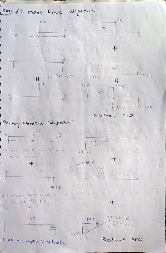
5. use the force method to determine the reactions at the support draw the Shear and...
USE THE FORCE METHOD TO DETERMINE THE REAGUONS THE SUPOORS, DRAW THE SHEAR AND MOMENT DIAGRAMS....
 USE THE FORCE METHOD TO DETERMINE THE REAGUONS THE SUPOORS, DRAW THE SHEAR AND MOMENT DIAGRAMS. ASSUME A IS FIXED AND B IS A ROLLER. EL s CONSTANT Ay = ? 20K Ax= ? Ma = ? S'O By: ?
force Method for frames
 Determine the support reactions using the force method. Draw the shear and moment diagrams. Assume support A as fixed and support C as a roller.
Q5: Using force method, determine the reactions of the supports for the beam shown in Figure...
 Q5: Using force method, determine the reactions of the
supports for the beam shown in Figure (5). Then draw shear and
bending moment diagrams for the beam. EI is constant. Use conjugate
beam method to determine deflections.
I need it in 30min or 1 h
6 m 50 KN 200 kN.m 22 А В. С 9 m to 3m
Q5: Using force method, determine the reactions of the
supports for the beam shown in Figure (5). Then draw shear and
bending moment diagrams for the beam. EI is constant. Use conjugate
beam method to determine deflections.
I need it in 30min or 1 h
6 m 50 KN 200 kN.m 22 А В. С 9 m to 3m
Determine the reactions and draw the shear and bending momentdiagram. Use the method of consistent...
 Determine the reactions and draw the shear and bending moment
diagram. Use the method of consistent deformations and select the
reaction at the roller support to be the redundant.
Determine the reactions and draw the shear and bending moment
diagram. Use the method of consistent deformations and select the
reaction at the roller support to be the redundant.
Draw the Shear Force (V) and Bending Moment (MI) diagrams of statically indeterminate beam shown in...
 Draw the Shear Force (V) and Bending Moment (MI) diagrams of statically indeterminate beam shown in figure using “Force Method”. The (roller) support at "B" settles 35 mm. The moment of inertia is given by (1) for regions "AB", "BC" and "CD"; however it is equal to (21) for the region “DE”. ("B" is the roller and “E" is the fixed type of support). [The flexural rigidity: EI=40000 kNm] 60 KN y 10 kN/m A - Tu (21) 1.5m 11...
Compute the reactions and draw the shear and moment curves for the beam below using slope-deflection...
 Compute the reactions and draw the shear and moment curves for
the beam below using slope-deflection method
2. Determine the moments at each support, then draw the moment diagram. Assume A is fixed. EI is constant. 12 k 4 k/ft 8 ft---8 ft
Compute the reactions and draw the shear and moment curves for
the beam below using slope-deflection method
2. Determine the moments at each support, then draw the moment diagram. Assume A is fixed. EI is constant. 12 k 4 k/ft 8 ft---8 ft
asap Q5: Using force method, determine the reactions of the supports for the beam shown in...
 asap
Q5: Using force method, determine the reactions of the supports for the beam shown in Figure (5). Then draw shear and bending moment diagrams for the beam. EI is constant. Use conjugate beam method to determine deflections. 6 m 50 KN 200 kN.m 9 m 3 m Fig. (5)
asap
Q5: Using force method, determine the reactions of the supports for the beam shown in Figure (5). Then draw shear and bending moment diagrams for the beam. EI is constant. Use conjugate beam method to determine deflections. 6 m 50 KN 200 kN.m 9 m 3 m Fig. (5)
Draw/ influence lines for shear to the left of A, shear at B, and moment at C.
 1-(25%) Draw shear and moment diagrams for the beam shown in Figure P-1. Draw a sketch of the deflected shape 2-(25%) Using moment area method, for the beam shown in Figure P-2 find deflection at A. Also, determine the location and value of the maximum deflection in span BC. El is constant 3-(25%) For the frame shown in Figure P-3-find member frees and draw shear and moment diagrams. 4-(25%) Draw/ influence lines for shear to the left of A, shear at B, and...
Part B) For the frame (no sidesway) below, determine the reactions and draw the shear and moment ...
 Part B) For the frame (no sidesway) below, determine the reactions and draw the shear and moment diagrams using the moment-distribution method of analysis. Joints A, B and E are fixed and all members are rigidly connected at C and D. You may perform the moment distribution by hand. E is constant, but I is as shown on the frame 50 kN 50 kN 4 m 6 kN/m 21 1.51 1.51 6 m 8 Part 3) Reanalyze the frame of...
Calculate.... 1. Calculate the support reactions and draw the axial force, shear force and bending moment...
 Calculate....
1. Calculate the support reactions and draw the axial force, shear force and bending moment diagrams for the beams and frame shown in Fig. 1, labelling all important values (such as, but not necessarily limited to, locations of points of inflection and values of shears and moments at supports, intersections and discontinuities). For the portal frame in li) assume there are points of inflection in the columns located 2.4m up from the ground and one in the beam midway...
Calculate....
1. Calculate the support reactions and draw the axial force, shear force and bending moment diagrams for the beams and frame shown in Fig. 1, labelling all important values (such as, but not necessarily limited to, locations of points of inflection and values of shears and moments at supports, intersections and discontinuities). For the portal frame in li) assume there are points of inflection in the columns located 2.4m up from the ground and one in the beam midway...
 USE THE FORCE METHOD TO DETERMINE THE REAGUONS THE SUPOORS, DRAW THE SHEAR AND MOMENT DIAGRAMS. ASSUME A IS FIXED AND B IS A ROLLER. EL s CONSTANT Ay = ? 20K Ax= ? Ma = ? S'O By: ?
 Q5: Using force method, determine the reactions of the
supports for the beam shown in Figure (5). Then draw shear and
bending moment diagrams for the beam. EI is constant. Use conjugate
beam method to determine deflections.
I need it in 30min or 1 h
6 m 50 KN 200 kN.m 22 А В. С 9 m to 3m
Q5: Using force method, determine the reactions of the
supports for the beam shown in Figure (5). Then draw shear and
bending moment diagrams for the beam. EI is constant. Use conjugate
beam method to determine deflections.
I need it in 30min or 1 h
6 m 50 KN 200 kN.m 22 А В. С 9 m to 3m
 Determine the reactions and draw the shear and bending moment
diagram. Use the method of consistent deformations and select the
reaction at the roller support to be the redundant.
Determine the reactions and draw the shear and bending moment
diagram. Use the method of consistent deformations and select the
reaction at the roller support to be the redundant.
 Draw the Shear Force (V) and Bending Moment (MI) diagrams of statically indeterminate beam shown in figure using “Force Method”. The (roller) support at "B" settles 35 mm. The moment of inertia is given by (1) for regions "AB", "BC" and "CD"; however it is equal to (21) for the region “DE”. ("B" is the roller and “E" is the fixed type of support). [The flexural rigidity: EI=40000 kNm] 60 KN y 10 kN/m A - Tu (21) 1.5m 11...
 Compute the reactions and draw the shear and moment curves for
the beam below using slope-deflection method
2. Determine the moments at each support, then draw the moment diagram. Assume A is fixed. EI is constant. 12 k 4 k/ft 8 ft---8 ft
Compute the reactions and draw the shear and moment curves for
the beam below using slope-deflection method
2. Determine the moments at each support, then draw the moment diagram. Assume A is fixed. EI is constant. 12 k 4 k/ft 8 ft---8 ft
 asap
Q5: Using force method, determine the reactions of the supports for the beam shown in Figure (5). Then draw shear and bending moment diagrams for the beam. EI is constant. Use conjugate beam method to determine deflections. 6 m 50 KN 200 kN.m 9 m 3 m Fig. (5)
asap
Q5: Using force method, determine the reactions of the supports for the beam shown in Figure (5). Then draw shear and bending moment diagrams for the beam. EI is constant. Use conjugate beam method to determine deflections. 6 m 50 KN 200 kN.m 9 m 3 m Fig. (5)
 Part B) For the frame (no sidesway) below, determine the reactions and draw the shear and moment diagrams using the moment-distribution method of analysis. Joints A, B and E are fixed and all members are rigidly connected at C and D. You may perform the moment distribution by hand. E is constant, but I is as shown on the frame 50 kN 50 kN 4 m 6 kN/m 21 1.51 1.51 6 m 8 Part 3) Reanalyze the frame of...
 Calculate....
1. Calculate the support reactions and draw the axial force, shear force and bending moment diagrams for the beams and frame shown in Fig. 1, labelling all important values (such as, but not necessarily limited to, locations of points of inflection and values of shears and moments at supports, intersections and discontinuities). For the portal frame in li) assume there are points of inflection in the columns located 2.4m up from the ground and one in the beam midway...
Calculate....
1. Calculate the support reactions and draw the axial force, shear force and bending moment diagrams for the beams and frame shown in Fig. 1, labelling all important values (such as, but not necessarily limited to, locations of points of inflection and values of shears and moments at supports, intersections and discontinuities). For the portal frame in li) assume there are points of inflection in the columns located 2.4m up from the ground and one in the beam midway...
Most questions answered within 3 hours.
-
Write a program to solve the Josephus problem, with the following
modification:
Sample Input:
./a.out n...
asked 2 hours ago -
At the start of a CD it is spinning at a rate of 525 rpm
(revolutions...
asked 3 hours ago -
4. Without doing any calculations, predict whether the observed
∆T would increase, decrease or remain the...
asked 4 hours ago -
Based on the range, which of the following sets of scores has
the greatest variability? 3,...
asked 5 hours ago -
Ripples in a pond travel at a velocity of 3 m/s with one peak
passing a...
asked 5 hours ago -
A man stands on the roof of a building of height 13.0 mm and
throws a...
asked 5 hours ago -
The extent to which assets are financed by borrowed funds and
other liabilities is indicated by:...
asked 6 hours ago -
Explain in detail
Germany is the fifth largest economy
explain what goods and services Germany specializes...
asked 6 hours ago -
The density of platinum is 21.45 g/mL. If a cube of platinum
with a mass of...
asked 6 hours ago -
Accounts Receivable
Sales
A/R Posting
Extended Sales Invoice
Packing Slip
Compare invoice to packing slip 2...
asked 6 hours ago -
Michaella, age 23, is a full-time law student and is claimed by
her parents as a...
asked 6 hours ago -
Why are polymers not typically casted into products?
asked 7 hours ago