
Homework Answers


Add Answer to:
Part B) For the frame (no sidesway) below, determine the reactions and draw the shear and moment ...
Problem Determine the reactions and draw the shear and bending moment diagrams for the beams shown...
 Problem Determine the reactions and draw the shear and bending moment diagrams for the beams shown in Figs. P16.8-P16.14 by using the moment-distribution method 120 kN 120 kN 150 kN m--4 21 E 200 GPa 1- 500 (106 mm
5. Draw the shear and moment diagrams for each member of the frame 6 kN/m B...
 5. Draw the shear and moment diagrams for each member of the frame 6 kN/m B 1.5 m 12 KN 1.5 m
Use moment distribution method or slope deflection method. The frame shown if Fig. 2.1 is supporting...
 Use moment distribution method or slope deflection
method.
The frame shown if Fig. 2.1 is supporting a lateral load of 60 kN and a gravity load of 50 kNIm. Neglect the weight of the members (a) Determine th reaction forces. (b) Draw the axial, shear, and bending moment and qualitative deflected shape diagrams of the frame. Specify values at a change of loading positions and at all points of zero shear and moment. Use slope-deflection method 2m Fig. 2.1 w...
Use moment distribution method or slope deflection
method.
The frame shown if Fig. 2.1 is supporting a lateral load of 60 kN and a gravity load of 50 kNIm. Neglect the weight of the members (a) Determine th reaction forces. (b) Draw the axial, shear, and bending moment and qualitative deflected shape diagrams of the frame. Specify values at a change of loading positions and at all points of zero shear and moment. Use slope-deflection method 2m Fig. 2.1 w...
CE 340-F/2016-EXAM 4. FRAME-SOLUTION BY MOMENT-DISTRIBUTION METHOD w-3.6 kips 21 to 20 Use the Moment-Distribution Method to analyze the braced-frame shown above (No Side-way). Note: Joints F an...
 CE 340-F/2016-EXAM 4. FRAME-SOLUTION BY MOMENT-DISTRIBUTION METHOD w-3.6 kips 21 to 20 Use the Moment-Distribution Method to analyze the braced-frame shown above (No Side-way). Note: Joints F and E are fixed; joints A and D are pin-connected; No loads on member DC. (Hint: Start at joint A) -Clearly show computations of stiffness values, K, and DFs. -Clearly show computations of FEMs. -Present a clear and organized table of iterations to follow your computation. A suggested table is given on the...
03: Given the statically indeterminate frame as shown in Fig. Q3 below, determine the member end...
 03: Given the statically indeterminate frame as shown in Fig. Q3 below, determine the member end moments and the support reactions of the frame using moment distribution method. Moment distribution to be done for 3 iterations of locking and unlocking cycle. A point load of 100KN is acting on span BC at 1/4 point of the span as shown. Support A and D are fixed supports. There is a roller support at joint C to prevent the frame from going...
QUESTION 2 (TOTAL 25 MARKS) A statically indeterminate frame is given in the figure below. El...
 QUESTION 2 (TOTAL 25 MARKS) A statically indeterminate frame is given in the figure below. El is constant for all members. Determine the member end moments of the frame using the moment distribution method. 5 kN/m BETTI 2. m mun. 10KN 2 m 8 m Note: The frame can be classified as a frame with sidesway. Stiffness factors 4EI. for a standard member for a member with a pin/roller end A table for fixed-end moments is given at the end...
make sure not to copy previous work For the frame shown below: 1- Calculate the reactions at the supports 2- Show the equilibrium at nodes B and C 3- Draw the normal force, the shear force and the...
 make sure not to copy previous work
For the frame shown below: 1- Calculate the reactions at the supports 2- Show the equilibrium at nodes B and C 3- Draw the normal force, the shear force and the bending moment diagrams 2 KN 3 KN 2 m 2 m 3 m 4 m
For the frame shown below: 1- Calculate the reactions at the supports 2- Show the equilibrium at nodes B and C 3- Draw the normal force, the...
make sure not to copy previous work
For the frame shown below: 1- Calculate the reactions at the supports 2- Show the equilibrium at nodes B and C 3- Draw the normal force, the shear force and the bending moment diagrams 2 KN 3 KN 2 m 2 m 3 m 4 m
For the frame shown below: 1- Calculate the reactions at the supports 2- Show the equilibrium at nodes B and C 3- Draw the normal force, the...
A frame structure is shown in Figure 1, in which points A, B and C are all pins (a) Draw the shear and moment diagrams...
 A frame structure is shown in Figure 1, in which points A, B and C are all pins (a) Draw the shear and moment diagrams for the frame, and determine the shear and moment at points D and E [20 marks] (b) Calculate the horizontal deflection of the frame at joint F use virtual-work. EI for all members are the same and is a constant. [20 marks] 0.25 m 0.75 m C D 0.75 m 0.75 m 00 N/m 60...
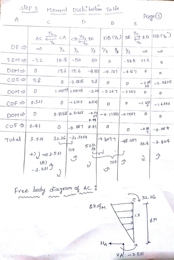
Moment distribution method Determine the moments at A, C, and D, then draw the moment diagram for each member of the...
 Moment distribution method
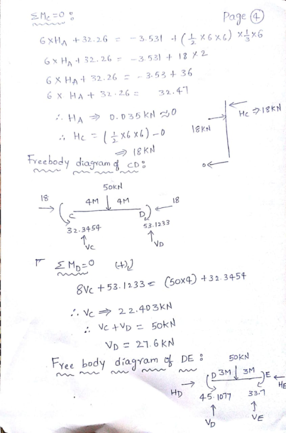
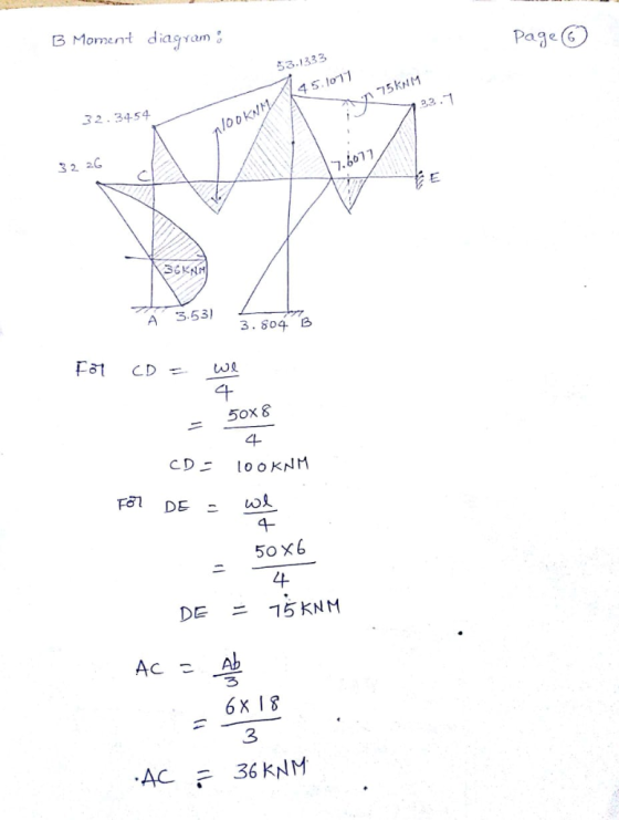
Determine the moments at A, C, and D, then draw the moment diagram for each member of the frame. Support A and joints C and D are fixed connected. El is constant Prob. 11-18 6 kN/m 6 m 8 m rn 7 m
Moment distribution method
Determine the moments at A, C, and D, then draw the moment diagram for each member of the frame. Support A and joints C and D are fixed connected. El is constant Prob. 11-18 6 kN/m 6 m 8 m rn 7 m
Use Moment Distribution to determine all final member-end-moments for the frames given below. With these moments...
 Use Moment Distribution to determine all final member-end-moments for the frames given below. With these moments and statics, find member-end-shears and axial forces, as well as all reactions. Draw shear moment and axial force diagrams. Note that the first frame does not sway but the 2nd frame can 85 kips 50 kips 30 kips 35 ft Pin ID E 90 ft o (Ctrl
 Problem Determine the reactions and draw the shear and bending moment diagrams for the beams shown in Figs. P16.8-P16.14 by using the moment-distribution method 120 kN 120 kN 150 kN m--4 21 E 200 GPa 1- 500 (106 mm
 5. Draw the shear and moment diagrams for each member of the frame 6 kN/m B 1.5 m 12 KN 1.5 m
 Use moment distribution method or slope deflection
method.
The frame shown if Fig. 2.1 is supporting a lateral load of 60 kN and a gravity load of 50 kNIm. Neglect the weight of the members (a) Determine th reaction forces. (b) Draw the axial, shear, and bending moment and qualitative deflected shape diagrams of the frame. Specify values at a change of loading positions and at all points of zero shear and moment. Use slope-deflection method 2m Fig. 2.1 w...
Use moment distribution method or slope deflection
method.
The frame shown if Fig. 2.1 is supporting a lateral load of 60 kN and a gravity load of 50 kNIm. Neglect the weight of the members (a) Determine th reaction forces. (b) Draw the axial, shear, and bending moment and qualitative deflected shape diagrams of the frame. Specify values at a change of loading positions and at all points of zero shear and moment. Use slope-deflection method 2m Fig. 2.1 w...
 CE 340-F/2016-EXAM 4. FRAME-SOLUTION BY MOMENT-DISTRIBUTION METHOD w-3.6 kips 21 to 20 Use the Moment-Distribution Method to analyze the braced-frame shown above (No Side-way). Note: Joints F and E are fixed; joints A and D are pin-connected; No loads on member DC. (Hint: Start at joint A) -Clearly show computations of stiffness values, K, and DFs. -Clearly show computations of FEMs. -Present a clear and organized table of iterations to follow your computation. A suggested table is given on the...
 03: Given the statically indeterminate frame as shown in Fig. Q3 below, determine the member end moments and the support reactions of the frame using moment distribution method. Moment distribution to be done for 3 iterations of locking and unlocking cycle. A point load of 100KN is acting on span BC at 1/4 point of the span as shown. Support A and D are fixed supports. There is a roller support at joint C to prevent the frame from going...
 QUESTION 2 (TOTAL 25 MARKS) A statically indeterminate frame is given in the figure below. El is constant for all members. Determine the member end moments of the frame using the moment distribution method. 5 kN/m BETTI 2. m mun. 10KN 2 m 8 m Note: The frame can be classified as a frame with sidesway. Stiffness factors 4EI. for a standard member for a member with a pin/roller end A table for fixed-end moments is given at the end...
 make sure not to copy previous work
For the frame shown below: 1- Calculate the reactions at the supports 2- Show the equilibrium at nodes B and C 3- Draw the normal force, the shear force and the bending moment diagrams 2 KN 3 KN 2 m 2 m 3 m 4 m
For the frame shown below: 1- Calculate the reactions at the supports 2- Show the equilibrium at nodes B and C 3- Draw the normal force, the...
make sure not to copy previous work
For the frame shown below: 1- Calculate the reactions at the supports 2- Show the equilibrium at nodes B and C 3- Draw the normal force, the shear force and the bending moment diagrams 2 KN 3 KN 2 m 2 m 3 m 4 m
For the frame shown below: 1- Calculate the reactions at the supports 2- Show the equilibrium at nodes B and C 3- Draw the normal force, the...
 A frame structure is shown in Figure 1, in which points A, B and C are all pins (a) Draw the shear and moment diagrams for the frame, and determine the shear and moment at points D and E [20 marks] (b) Calculate the horizontal deflection of the frame at joint F use virtual-work. EI for all members are the same and is a constant. [20 marks] 0.25 m 0.75 m C D 0.75 m 0.75 m 00 N/m 60...
 Moment distribution method
Determine the moments at A, C, and D, then draw the moment diagram for each member of the frame. Support A and joints C and D are fixed connected. El is constant Prob. 11-18 6 kN/m 6 m 8 m rn 7 m
Moment distribution method
Determine the moments at A, C, and D, then draw the moment diagram for each member of the frame. Support A and joints C and D are fixed connected. El is constant Prob. 11-18 6 kN/m 6 m 8 m rn 7 m
 Use Moment Distribution to determine all final member-end-moments for the frames given below. With these moments and statics, find member-end-shears and axial forces, as well as all reactions. Draw shear moment and axial force diagrams. Note that the first frame does not sway but the 2nd frame can 85 kips 50 kips 30 kips 35 ft Pin ID E 90 ft o (Ctrl
Most questions answered within 3 hours.
-
without using map
1. Write a C++ program to find out the top 10 words in...
asked 1 minute ago -
A physics major is cooking breakfast when he notices that the
frictional force between the steel...
asked 5 minutes ago -
1)Calculate the percent ionization of a
0.330 M solution of hypochlorous
acid.
% Ionization = %...
asked 3 minutes ago -
A cyclohexane (c-hex) solution is prepared by fully dissolving
9.11g of a newly synthesized organic compound...
asked 11 minutes ago -
SCHEME :-)
[5 marks] Write a procedure called convert that takes as
arguments: a temperature value...
asked 17 minutes ago -
Are
Acetyl CoA and Pyruvate biological molecules that are used to get
ATP energy in aerobic...
asked 18 minutes ago -
Two waves are traveling on a string, one with a wave function,
y1 = 0.05sin(4x -...
asked 25 minutes ago -
Develop an ideal customer profile for three Dell Customer
groups( a supplier, a global business, and...
asked 28 minutes ago -
Suppose, for any future year, the probability its October rain
is more than 3 inches is...
asked 32 minutes ago -
Solve the following systems of linear equations using
substitution 12p + 3q = 15 6q +...
asked 39 minutes ago -
Prof. D went grocery shopping and purchased one dozen eggs and
one pound of flour (all...
asked 47 minutes ago -
If
somehow loop of Henle were removed - that is if the proximal tubule
was connected...
asked 47 minutes ago