PLEASE FAST I HAVE 15 MINS LEFT !!
![Question 1: [50 Marks] For the frame shown, draw the bending moment diagram for each member. 40 kN/m 60 kN E D 80 KN 3 m 540](http://img.homeworklib.com/questions/5d75b2c0-f154-11ea-9b65-e58a5a9d3b4a.png?x-oss-process=image/resize,w_560)
Homework Answers

Add Answer to:
PLEASE FAST I HAVE 15 MINS LEFT !!
Question 1: [50 Marks] For the frame shown,...
For the frame shown, draw the bending moment diagram for each member. 40 kN/m 60 KN...
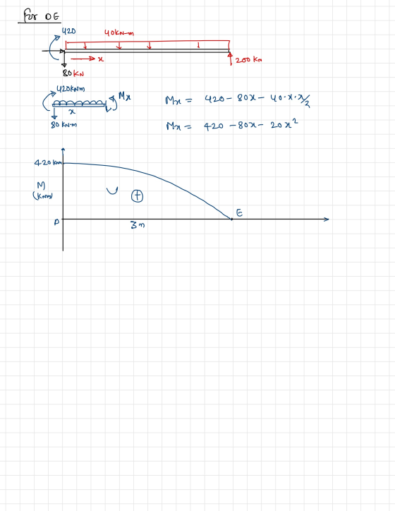
 For the frame shown, draw the bending moment diagram for each member. 40 kN/m 60 KN E D 80 KN 3 m с 540 kN.m B 3 m A 1.5 m 3 m
For the frame shown, draw the bending moment diagram for each member. 40 kN/m 60 KN...
 For the frame shown, draw the bending moment diagram for each member. 40 kN/m 60 KN E D 80 KN 3 m С 540 kN.m B 3 m A 1.5 m 3 m
PLEASE FAST I HAVE 15 MINS LEFT !! Question 2: [50 Marks] For the beam shown,...
 PLEASE FAST I HAVE 15 MINS LEFT !!
Question 2: [50 Marks] For the beam shown, use the Conjugate Beam Method to determine a) The deflection at F, b) The slopes on both sides of the hinge at C. 90 KN 160 kN.m E B C D F 2 m 2 m 2 m 2 m 2 m EI = Constant
PLEASE FAST I HAVE 15 MINS LEFT !!
Question 2: [50 Marks] For the beam shown, use the Conjugate Beam Method to determine a) The deflection at F, b) The slopes on both sides of the hinge at C. 90 KN 160 kN.m E B C D F 2 m 2 m 2 m 2 m 2 m EI = Constant
For the frame shown, draw the bending moment diagram for each member. 40 kN/m 60 KN...
 For the frame shown, draw the bending moment diagram for each member. 40 kN/m 60 KN E D 80 KN 3 m C 540 kN.m B 3 m А 1.5 m 3 m
For the frame shown, draw the bending moment diagram for each member. 40 kN/m 60 KN...
 For the frame shown, draw the bending moment diagram for each member. 40 kN/m 60 KN E D 80 KN 3 m 540 kN.m C B 3 m А 1.5 m 3 m
please solve it as soon as possible Q3) For the frame shown. Determine the member end...
 please solve it as soon as possible
Q3) For the frame shown. Determine the member end moments and draw the bending moment diagram (with value). EI - 5000 KN.m ta
please solve it as soon as possible
Q3) For the frame shown. Determine the member end moments and draw the bending moment diagram (with value). EI - 5000 KN.m ta
QUESTION 1 [25 marks A frame loaded with a uniformly distributed load at Member AB and...
 QUESTION 1 [25 marks A frame loaded with a uniformly distributed load at Member AB and point load at Member BC and joint B. It has pinned supports A and C, while joint B is fixed connected, as can be seen in Figure 1. Take E-200 GPa. a) Using the slope-deflection method, calculate the moments and illustrate the bending moment diagram. [15 marks) b) Then calculate the shear forces and sketch the shear force diagram. [10 marks) 22 KN 10...
For the frame shown. use the slope-deflection method to (a) Determine the end moments of each...
 For the frame shown. use the slope-deflection method to (a) Determine the end moments of each member and reactions at supports (b) Draw the quantitative bending moment diagram. and also draw the qualitative deflected shape of the entire frame. 10 kN 12 kN/m 2EI 3 m 40 KN 3 m 6 m
Any one Can solve this Fast please i need it now Q5: Using force method, determine...
 Any one Can solve this Fast please i need it
now
Q5: Using force method, determine the reactions of the supports for the beam shown in Figure (5). Then draw shear and bending moment diagrams for the beam. El is constant Use conjugate beam method to determine deflections. 6 m 50 KN 200 kN.m 2 B 9 m
Any one Can solve this Fast please i need it
now
Q5: Using force method, determine the reactions of the supports for the beam shown in Figure (5). Then draw shear and bending moment diagrams for the beam. El is constant Use conjugate beam method to determine deflections. 6 m 50 KN 200 kN.m 2 B 9 m
Question 1 (a) Abeam has a fixed support at A and roller supports at D and E as shown in Fig. Q.la below. Internal...
 Question 1 (a) Abeam has a fixed support at A and roller supports at D and E as shown in Fig. Q.la below. Internal hinges are also placed at B and C. (i) Determine all the reactions (ii) Draw the shear force diagram for the beam. (iii) Draw the bending moment diagram for the beam. (20%) (25%) (25° 60 kN/m 40 kN/m 20 kN/m 150 kN 100 kN.m Hinge Fig. Q.1a
 For the frame shown, draw the bending moment diagram for each member. 40 kN/m 60 KN E D 80 KN 3 m с 540 kN.m B 3 m A 1.5 m 3 m
 For the frame shown, draw the bending moment diagram for each member. 40 kN/m 60 KN E D 80 KN 3 m С 540 kN.m B 3 m A 1.5 m 3 m
 PLEASE FAST I HAVE 15 MINS LEFT !!
Question 2: [50 Marks] For the beam shown, use the Conjugate Beam Method to determine a) The deflection at F, b) The slopes on both sides of the hinge at C. 90 KN 160 kN.m E B C D F 2 m 2 m 2 m 2 m 2 m EI = Constant
PLEASE FAST I HAVE 15 MINS LEFT !!
Question 2: [50 Marks] For the beam shown, use the Conjugate Beam Method to determine a) The deflection at F, b) The slopes on both sides of the hinge at C. 90 KN 160 kN.m E B C D F 2 m 2 m 2 m 2 m 2 m EI = Constant
 For the frame shown, draw the bending moment diagram for each member. 40 kN/m 60 KN E D 80 KN 3 m C 540 kN.m B 3 m А 1.5 m 3 m
 For the frame shown, draw the bending moment diagram for each member. 40 kN/m 60 KN E D 80 KN 3 m 540 kN.m C B 3 m А 1.5 m 3 m
 please solve it as soon as possible
Q3) For the frame shown. Determine the member end moments and draw the bending moment diagram (with value). EI - 5000 KN.m ta
please solve it as soon as possible
Q3) For the frame shown. Determine the member end moments and draw the bending moment diagram (with value). EI - 5000 KN.m ta
 QUESTION 1 [25 marks A frame loaded with a uniformly distributed load at Member AB and point load at Member BC and joint B. It has pinned supports A and C, while joint B is fixed connected, as can be seen in Figure 1. Take E-200 GPa. a) Using the slope-deflection method, calculate the moments and illustrate the bending moment diagram. [15 marks) b) Then calculate the shear forces and sketch the shear force diagram. [10 marks) 22 KN 10...
 For the frame shown. use the slope-deflection method to (a) Determine the end moments of each member and reactions at supports (b) Draw the quantitative bending moment diagram. and also draw the qualitative deflected shape of the entire frame. 10 kN 12 kN/m 2EI 3 m 40 KN 3 m 6 m
 Any one Can solve this Fast please i need it
now
Q5: Using force method, determine the reactions of the supports for the beam shown in Figure (5). Then draw shear and bending moment diagrams for the beam. El is constant Use conjugate beam method to determine deflections. 6 m 50 KN 200 kN.m 2 B 9 m
Any one Can solve this Fast please i need it
now
Q5: Using force method, determine the reactions of the supports for the beam shown in Figure (5). Then draw shear and bending moment diagrams for the beam. El is constant Use conjugate beam method to determine deflections. 6 m 50 KN 200 kN.m 2 B 9 m
 Question 1 (a) Abeam has a fixed support at A and roller supports at D and E as shown in Fig. Q.la below. Internal hinges are also placed at B and C. (i) Determine all the reactions (ii) Draw the shear force diagram for the beam. (iii) Draw the bending moment diagram for the beam. (20%) (25%) (25° 60 kN/m 40 kN/m 20 kN/m 150 kN 100 kN.m Hinge Fig. Q.1a
Most questions answered within 3 hours.
-
The manager at a car assembly plant believes that the mean
assembly time for a car...
asked 36 minutes ago -
Which of the following is true of electron capture?
A) It decreases the nuclide's mass number...
asked 2 hours ago -
Assuming an efficiency of 43.10%, calculate the actual yield of
magnesium nitrate formed from 114.9 g...
asked 2 hours ago -
The highly pathogenic bacterium Clostridium
perfringens causes gangrene, a disease that results in the
destruction of...
asked 4 hours ago -
In the context of situation analysis, which of the following is
a category for analysis in...
asked 4 hours ago -
In a study of the gas phase decomposition of sulfuryl chloride
at 600 K SO2Cl2(g)SO2(g) +...
asked 4 hours ago -
75 g of 2-propanol (C3H8O) and 25 g of pentane are mixed in a
200 mL...
asked 4 hours ago -
The 2800-turn coil in a dc motor has an area per turn of 1.1 ×
10-2...
asked 4 hours ago -
Draw a combinational logic circuit diagram with a symbol inside
the box for two I/P of...
asked 4 hours ago -
The cliché we use quite a lot in finance is: there is a need to
maximize...
asked 4 hours ago -
In class we discussed the addition of HCl to alpha pinene. Would
you expect one or...
asked 4 hours ago -
I'm trying to explain to my daughter to help her please help
me
I tagged the...
asked 5 hours ago