

Homework Answers


Add Answer to:
The tension member shown in Figure 1 is subjected to a tensile force T. The member...
Figure 1 shows a bolted truss connection used in the construction of a roof system for...
 Figure 1 shows a bolted truss connection used in the construction of a roof system for a large industrial building. The diagonal members of the truss are 150 x 150 x 12 Equal Angies (Grade 300). They are bolted to a 16 mm gusset plate using 8 M20 Grade 8.8/S bolts. a) What is the axial tension design capacity of the connection? (Assume that the 16 mm gusset plate is the strongest component and will not fail) (12 Marks) b)...
For the tension member shown below, determino the maximum tenslon force Tu that ma applied and...
 For the tension member shown below, determino the maximum tenslon force Tu that ma applied and meet the following requirements of the AISC Manual: (s P a. Tensile Yielding 1. b. Tensile Rupture c. Bolt Shear d. Bearing at Bolt Hole 1-1'4 A35 GusseT L16 (ASTAM A30) L6XYK AS1M A36 MA1'L GAEE 31
For the tension member shown below, determino the maximum tenslon force Tu that ma applied and meet the following requirements of the AISC Manual: (s P a....
For the tension member shown below, determino the maximum tenslon force Tu that ma applied and meet the following requirements of the AISC Manual: (s P a. Tensile Yielding 1. b. Tensile Rupture c. Bolt Shear d. Bearing at Bolt Hole 1-1'4 A35 GusseT L16 (ASTAM A30) L6XYK AS1M A36 MA1'L GAEE 31
For the tension member shown below, determino the maximum tenslon force Tu that ma applied and meet the following requirements of the AISC Manual: (s P a....
Question 1: Three tension members are shown below. Assume the strength of the member controls and...
 Question 1: Three tension members are shown below. Assume the strength of the member controls and not the connecting element. Each member is made from A36 steel. All bolts are spaced at 3.0 inches unless the sketch indicates otherwise. The distance from the centerline of the last bolt to the end of the tension member is 2.0 inches unless the sketch indicates otherwise. The required sketches described below are 20% of the points Include the following: For the area calculations...
An L5x5x1/2 tension member of A588 steel is connected to a gusset plate with ¾-in diameter...
 An L5x5x1/2 tension member of A588 steel is connected to a
gusset plate with ¾-in diameter bolts as shown in Figure 1. Assume
block shear is not a concern. Use the alternative value of U from
AISC Table D3.1
a.) The LRFD tension rupture strength (Pn) of the member
is?
b.) The LRFD tension strength (Pn) of the member is?
L5x5x22 OOOOOO 1S w befo-soprano-belim 5 spaces @ 3" - = 15" Figure 1
An L5x5x1/2 tension member of A588 steel is connected to a
gusset plate with ¾-in diameter bolts as shown in Figure 1. Assume
block shear is not a concern. Use the alternative value of U from
AISC Table D3.1
a.) The LRFD tension rupture strength (Pn) of the member
is?
b.) The LRFD tension strength (Pn) of the member is?
L5x5x22 OOOOOO 1S w befo-soprano-belim 5 spaces @ 3" - = 15" Figure 1
1) Determine the force in member BE and state if the member is in tension or...
 1) Determine the force in member BE and state if the
member is in tension or compression.
2) Determine the force in member EF and state if the
member is in tension or compression.
3) Determine the force in member CB and state if the
member is in tension or compression.
Consider the truss shown in (Figure 1). Suppose that F1 = 6 kN and F2 = 10 kN. Figure 1 of 1 4 m E 4 m B F...
1) Determine the force in member BE and state if the
member is in tension or compression.
2) Determine the force in member EF and state if the
member is in tension or compression.
3) Determine the force in member CB and state if the
member is in tension or compression.
Consider the truss shown in (Figure 1). Suppose that F1 = 6 kN and F2 = 10 kN. Figure 1 of 1 4 m E 4 m B F...
PartA Consider the truss shown in (Figure 1). Suppose that F 13 kN Determine the force in member CD and state if this member is in tension or compression. Express your answer to three significant fig...
 PartA Consider the truss shown in (Figure 1). Suppose that F 13 kN Determine the force in member CD and state if this member is in tension or compression. Express your answer to three significant figures and include the appropriate units. Enter negative value in the case of compression and positive value in the case of tension. FcValue Units CD = Submit Request Answer Figure 1 of 1 Part B Determine the force in member CJ and state if this...
Consider the truss shown in (Figure 1). Suppose that F-4 kN and Fa = 9 kN 1 of 1 Figure 4 m 4 m ▼ Part A Determine the force in member BE and state if the member is in tension or compression E...
 Consider the truss shown in (Figure 1). Suppose that F-4 kN and Fa = 9 kN 1 of 1 Figure 4 m 4 m ▼ Part A Determine the force in member BE and state if the member is in tension or compression Express your answer to three significant figures and include the appropriate units. Enter negative value in the case of compression and positive value in the case of tension. Part B Determine the force in member EF and...
As shown in Figure 8, the structural member (beam) is 7m long, carries a 2 kN point load, a 1.2 kN/m uniformly distribu...
 As shown in Figure 8, the structural member (beam) is 7m long, carries a 2 kN point load, a 1.2 kN/m uniformly distributed load and is supported at points A and B. The beam is constructed from two pieces of steel plate (2 at 80mm x 8mm) that are welded together with 3mm welds. Section properties for the beam are also listed. Given the support reactions as RAv 5.8 kN and RBv 2.2 kN, as well as the shear force...
1 Review Part A Consider the truss shown in (Figure 1). Assume the diagonals can support...
 1 Review Part A Consider the truss shown in (Figure 1). Assume the diagonals can support either a tensile or a compressive force. Suppose that P = 4k P2 = 6 k, P3 = 5 k. Determine (approximately) the force in member CD of the truss. State if the member is in tension or compression. Express your answer using three significant figures. Enter negative value in the case of compression and positive value in the case of tension. O AEQ...
Blem 2. (70 points) 1. For the beam shown in Figure (a): a) b) draw the shear force and bending m...
 blem 2. (70 points) 1. For the beam shown in Figure (a): a) b) draw the shear force and bending moment diagrams. (30 points) Select the most economical W shape for the beam with an allowable bending stress of 30 ksi. (10 points) determine the maximum tensile and compressive bending stresses at any location along the beam if the section shown in Figure (b) is used instead of the W shape section selectedin Part b. Would the beam be safe...
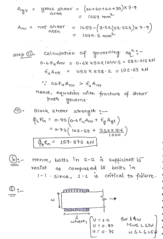
 Figure 1 shows a bolted truss connection used in the construction of a roof system for a large industrial building. The diagonal members of the truss are 150 x 150 x 12 Equal Angies (Grade 300). They are bolted to a 16 mm gusset plate using 8 M20 Grade 8.8/S bolts. a) What is the axial tension design capacity of the connection? (Assume that the 16 mm gusset plate is the strongest component and will not fail) (12 Marks) b)...
 For the tension member shown below, determino the maximum tenslon force Tu that ma applied and meet the following requirements of the AISC Manual: (s P a. Tensile Yielding 1. b. Tensile Rupture c. Bolt Shear d. Bearing at Bolt Hole 1-1'4 A35 GusseT L16 (ASTAM A30) L6XYK AS1M A36 MA1'L GAEE 31
For the tension member shown below, determino the maximum tenslon force Tu that ma applied and meet the following requirements of the AISC Manual: (s P a....
For the tension member shown below, determino the maximum tenslon force Tu that ma applied and meet the following requirements of the AISC Manual: (s P a. Tensile Yielding 1. b. Tensile Rupture c. Bolt Shear d. Bearing at Bolt Hole 1-1'4 A35 GusseT L16 (ASTAM A30) L6XYK AS1M A36 MA1'L GAEE 31
For the tension member shown below, determino the maximum tenslon force Tu that ma applied and meet the following requirements of the AISC Manual: (s P a....
 Question 1: Three tension members are shown below. Assume the strength of the member controls and not the connecting element. Each member is made from A36 steel. All bolts are spaced at 3.0 inches unless the sketch indicates otherwise. The distance from the centerline of the last bolt to the end of the tension member is 2.0 inches unless the sketch indicates otherwise. The required sketches described below are 20% of the points Include the following: For the area calculations...
 An L5x5x1/2 tension member of A588 steel is connected to a
gusset plate with ¾-in diameter bolts as shown in Figure 1. Assume
block shear is not a concern. Use the alternative value of U from
AISC Table D3.1
a.) The LRFD tension rupture strength (Pn) of the member
is?
b.) The LRFD tension strength (Pn) of the member is?
L5x5x22 OOOOOO 1S w befo-soprano-belim 5 spaces @ 3" - = 15" Figure 1
An L5x5x1/2 tension member of A588 steel is connected to a
gusset plate with ¾-in diameter bolts as shown in Figure 1. Assume
block shear is not a concern. Use the alternative value of U from
AISC Table D3.1
a.) The LRFD tension rupture strength (Pn) of the member
is?
b.) The LRFD tension strength (Pn) of the member is?
L5x5x22 OOOOOO 1S w befo-soprano-belim 5 spaces @ 3" - = 15" Figure 1
 1) Determine the force in member BE and state if the
member is in tension or compression.
2) Determine the force in member EF and state if the
member is in tension or compression.
3) Determine the force in member CB and state if the
member is in tension or compression.
Consider the truss shown in (Figure 1). Suppose that F1 = 6 kN and F2 = 10 kN. Figure 1 of 1 4 m E 4 m B F...
1) Determine the force in member BE and state if the
member is in tension or compression.
2) Determine the force in member EF and state if the
member is in tension or compression.
3) Determine the force in member CB and state if the
member is in tension or compression.
Consider the truss shown in (Figure 1). Suppose that F1 = 6 kN and F2 = 10 kN. Figure 1 of 1 4 m E 4 m B F...
 PartA Consider the truss shown in (Figure 1). Suppose that F 13 kN Determine the force in member CD and state if this member is in tension or compression. Express your answer to three significant figures and include the appropriate units. Enter negative value in the case of compression and positive value in the case of tension. FcValue Units CD = Submit Request Answer Figure 1 of 1 Part B Determine the force in member CJ and state if this...
 Consider the truss shown in (Figure 1). Suppose that F-4 kN and Fa = 9 kN 1 of 1 Figure 4 m 4 m ▼ Part A Determine the force in member BE and state if the member is in tension or compression Express your answer to three significant figures and include the appropriate units. Enter negative value in the case of compression and positive value in the case of tension. Part B Determine the force in member EF and...
 As shown in Figure 8, the structural member (beam) is 7m long, carries a 2 kN point load, a 1.2 kN/m uniformly distributed load and is supported at points A and B. The beam is constructed from two pieces of steel plate (2 at 80mm x 8mm) that are welded together with 3mm welds. Section properties for the beam are also listed. Given the support reactions as RAv 5.8 kN and RBv 2.2 kN, as well as the shear force...
 1 Review Part A Consider the truss shown in (Figure 1). Assume the diagonals can support either a tensile or a compressive force. Suppose that P = 4k P2 = 6 k, P3 = 5 k. Determine (approximately) the force in member CD of the truss. State if the member is in tension or compression. Express your answer using three significant figures. Enter negative value in the case of compression and positive value in the case of tension. O AEQ...
 blem 2. (70 points) 1. For the beam shown in Figure (a): a) b) draw the shear force and bending moment diagrams. (30 points) Select the most economical W shape for the beam with an allowable bending stress of 30 ksi. (10 points) determine the maximum tensile and compressive bending stresses at any location along the beam if the section shown in Figure (b) is used instead of the W shape section selectedin Part b. Would the beam be safe...
Most questions answered within 3 hours.
-
Derive ground state term symbols. Use notation 2S(1/2) for state
2S1/2
a) d5
b) f3
c)...
asked 6 seconds from now -
A sample of size 31 will be drawn from a population with mean 39
and standard...
asked 39 minutes ago -
What is the effect on the P-value when a test is changed from a
two-tailed hypothesis...
asked 43 minutes ago -
I wish to estimate µ, the mean of a population. After I collect
and an-
alyze...
asked 1 hour ago -
At a local university, you poll a group of 115 students and find
that 37 of...
asked 53 minutes ago -
Gladstone company tracks the number of units purchased and sold
throughout each accounting period but applies...
asked 56 minutes ago -
When determining if a molecule's configuration is E or Z, what
determines the higher priority groups?
asked 1 hour ago -
13. What is the amount
of conversion cost transferred to finished goods? (Round
your intermediate calculations...
asked 1 hour ago -
Sulfuric Acid is a "strong" acid, but only releases a single
proton when it dissolves. What...
asked 1 hour ago -
The
second floor of a house is 6 m above the street level. How much
work...
asked 1 hour ago -
What uncontrollable factor(s) contributed to Hong Kong Disney’s
poor performance during its first year?
asked 1 hour ago -
You are interested in whether students that have a male
instructors perform differently on exams. To...
asked 1 hour ago