
Homework Answers
Add Answer to:
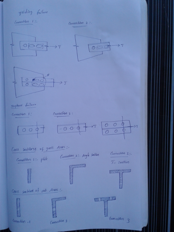
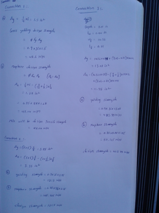
Question 1: Three tension members are shown below. Assume the strength of the member controls and...
ints) The connection below is a slip-critical connection. Calculate the design strength of the n assuming...
 ints) The connection below is a slip-critical connection. Calculate the design strength of the n assuming 7/8-in A325 bolts (threads excluded) with a factor for fillers, hf -1.0 Assume A36 steel tes, Class 8 faying surface and standard size holes. Check a. Gross section yielding of plates b. Tensile rupture of plates c. Slip-critical strength of bolts d. Bearing strength of bolts e. Shearing strength of the bolts f. Block Shear (Draw how the block 3 in 3 in o...
Design the lightest available W14 (A992) tension member by the 2016 AISC LRFD for a truss...
 Design the lightest available W14 (A992) tension member by the 2016 AISC LRFD for a truss that will carry service DL = 100 kips and service LL = 320 kips. The member is 30 ft. long. The flanges will be bolted to the connection plates (A36) with -in bolts so that four bolts will appear on the cross-section Assume there are at least three bolts per line, standard holes, and the connection is adequate. Hint: Consider all applicable limit states.
For the tension member shown below, determino the maximum tenslon force Tu that ma applied and...
 For the tension member shown below, determino the maximum tenslon force Tu that ma applied and meet the following requirements of the AISC Manual: (s P a. Tensile Yielding 1. b. Tensile Rupture c. Bolt Shear d. Bearing at Bolt Hole 1-1'4 A35 GusseT L16 (ASTAM A30) L6XYK AS1M A36 MA1'L GAEE 31
For the tension member shown below, determino the maximum tenslon force Tu that ma applied and meet the following requirements of the AISC Manual: (s P a....
For the tension member shown below, determino the maximum tenslon force Tu that ma applied and meet the following requirements of the AISC Manual: (s P a. Tensile Yielding 1. b. Tensile Rupture c. Bolt Shear d. Bearing at Bolt Hole 1-1'4 A35 GusseT L16 (ASTAM A30) L6XYK AS1M A36 MA1'L GAEE 31
For the tension member shown below, determino the maximum tenslon force Tu that ma applied and meet the following requirements of the AISC Manual: (s P a....
The tension member shown in Figure 1 is subjected to a tensile force T. The member...
 The tension member shown in Figure 1 is subjected to a tensile force T. The member has an L89x89x7.9 cross-section with 350W steel. The member is connected to a gusset plate through four A325 bolts having 3/4"(19 mm) diameter as shown. The threading can be assumed to intercept the plane of shear and the connection is short. The dimensions taken are a=30mm, b=60mm, and c=40mm. (a) Determine the tensile resistance of the member based on the potential failure trajectories 1-1...
S- Section FIGURE P3.2-3 APL⅜x6tension member is steel is A36. Assume that A, A, and compute...
 S- Section FIGURE P3.2-3 APL⅜x6tension member is steel is A36. Assume that A, A, and compute the following. a. The design strength for LRFD. b. The allowable strength for ASD. 32-4 APLx6 tension member is welded to a gusset plate as shown in Figure P3.2-4. The :and compute 3.2-4 ameter bolts, as shown A,A, and compute the FIGURE P3.2-4 ion member shown in Figure P3.2.5 is a PL tax 8 of A36 steel. The mem- ted to a gusset plate...
2. (30 pts) Determine the block shear strength of the tension member shown below. Bolts diameter...
 2. (30 pts) Determine the block shear strength of the tension member shown below. Bolts diameter = 7/8 in, A36 steel is used (Table 2-4 XN, A16 s 58 kse DO 3232 -in. bolts 19 (3) /8" bolts 3" bolt spacing (fy = 36 ksi P. 2-487 (Table 1-7) Ag = 2.50 in ² p. 1-48 - 1.00 in t. 3/8" And = [3.5"-(7/6" + /6")] (3/8") = 10.94 in? Ag. = (7.5") (2/6") - 2.81 in? Anu = [7.5...
2_...-3.5.1.3.5. 1 2 Q.4. A C7 x 9.8 tension member is connected to a 2/7-in.-thick gusset...
 2_...-3.5.1.3.5. 1 2 Q.4. A C7 x 9.8 tension member is connected to a 2/7-in.-thick gusset plate. Both the member and the gusset plate are A36 steel C79.8 O o o a) (15%) Compute the available block shear strength of the tension member for LRFD b) (10%) Compute the available block shear strength of the gusset plate for LRFD t-217 Wh-diameter bolts
Determine the design capacity, P that the W10x33 hanger shown below will support. Consider only the...
 Determine the design capacity, P that the W10x33 hanger shown below will support. Consider only the W10x33 on grid-line B and assume all other members and connections are satisfactory. Material is A992 and bolts are inch diameter. Show all calculations and identify each step for credit. Clearly state and justify any assumptions. 1- Determine the design strength of the member for cross yielding: 2- Determine the design strength of the member in net rupture: W24x68 W24x68 workable I9age W10x33 W24...
True of False 1.If a material point has three principal stresses ?1 = ?2 = ?3...
True of False 1.If a material point has three principal stresses ?1 = ?2 = ?3 = 300????, then the maximum shear stress is ???? = 150????. 2.The endurance limit of a material is independent on the size of a part. 3.The tensile stress in a bolt is usually calculated through tensile force divided by area of unthreaded rod’s cross-section area. 4.Edge shear-out or tear-out is one failure mode in bolted or riveted joints. 5.Pretension of bolts can be controlled...
Problem 1. Strength analysis of the statically undetermined bar system at tension (compression) Design the plane bar system for supporting of a rigid beam. Accept that the all bars have the same cross...
 Problem 1.
Strength analysis of the statically undetermined bar system at
tension (compression) Design the plane bar system for supporting of
a rigid beam.
Accept that the all bars have the same cross-sectional area and
made of the same material:
1) Calculate the axial forces in the cross-section of bars
2) Define the cross-section area of bars due the strength
condition
3) Calculate the extension of bars Scheme of system and input
data are given below
Scneme of system and...
Problem 1.
Strength analysis of the statically undetermined bar system at
tension (compression) Design the plane bar system for supporting of
a rigid beam.
Accept that the all bars have the same cross-sectional area and
made of the same material:
1) Calculate the axial forces in the cross-section of bars
2) Define the cross-section area of bars due the strength
condition
3) Calculate the extension of bars Scheme of system and input
data are given below
Scneme of system and...
 ints) The connection below is a slip-critical connection. Calculate the design strength of the n assuming 7/8-in A325 bolts (threads excluded) with a factor for fillers, hf -1.0 Assume A36 steel tes, Class 8 faying surface and standard size holes. Check a. Gross section yielding of plates b. Tensile rupture of plates c. Slip-critical strength of bolts d. Bearing strength of bolts e. Shearing strength of the bolts f. Block Shear (Draw how the block 3 in 3 in o...
 Design the lightest available W14 (A992) tension member by the 2016 AISC LRFD for a truss that will carry service DL = 100 kips and service LL = 320 kips. The member is 30 ft. long. The flanges will be bolted to the connection plates (A36) with -in bolts so that four bolts will appear on the cross-section Assume there are at least three bolts per line, standard holes, and the connection is adequate. Hint: Consider all applicable limit states.
 For the tension member shown below, determino the maximum tenslon force Tu that ma applied and meet the following requirements of the AISC Manual: (s P a. Tensile Yielding 1. b. Tensile Rupture c. Bolt Shear d. Bearing at Bolt Hole 1-1'4 A35 GusseT L16 (ASTAM A30) L6XYK AS1M A36 MA1'L GAEE 31
For the tension member shown below, determino the maximum tenslon force Tu that ma applied and meet the following requirements of the AISC Manual: (s P a....
For the tension member shown below, determino the maximum tenslon force Tu that ma applied and meet the following requirements of the AISC Manual: (s P a. Tensile Yielding 1. b. Tensile Rupture c. Bolt Shear d. Bearing at Bolt Hole 1-1'4 A35 GusseT L16 (ASTAM A30) L6XYK AS1M A36 MA1'L GAEE 31
For the tension member shown below, determino the maximum tenslon force Tu that ma applied and meet the following requirements of the AISC Manual: (s P a....
 The tension member shown in Figure 1 is subjected to a tensile force T. The member has an L89x89x7.9 cross-section with 350W steel. The member is connected to a gusset plate through four A325 bolts having 3/4"(19 mm) diameter as shown. The threading can be assumed to intercept the plane of shear and the connection is short. The dimensions taken are a=30mm, b=60mm, and c=40mm. (a) Determine the tensile resistance of the member based on the potential failure trajectories 1-1...
 S- Section FIGURE P3.2-3 APL⅜x6tension member is steel is A36. Assume that A, A, and compute the following. a. The design strength for LRFD. b. The allowable strength for ASD. 32-4 APLx6 tension member is welded to a gusset plate as shown in Figure P3.2-4. The :and compute 3.2-4 ameter bolts, as shown A,A, and compute the FIGURE P3.2-4 ion member shown in Figure P3.2.5 is a PL tax 8 of A36 steel. The mem- ted to a gusset plate...
 2. (30 pts) Determine the block shear strength of the tension member shown below. Bolts diameter = 7/8 in, A36 steel is used (Table 2-4 XN, A16 s 58 kse DO 3232 -in. bolts 19 (3) /8" bolts 3" bolt spacing (fy = 36 ksi P. 2-487 (Table 1-7) Ag = 2.50 in ² p. 1-48 - 1.00 in t. 3/8" And = [3.5"-(7/6" + /6")] (3/8") = 10.94 in? Ag. = (7.5") (2/6") - 2.81 in? Anu = [7.5...
 2_...-3.5.1.3.5. 1 2 Q.4. A C7 x 9.8 tension member is connected to a 2/7-in.-thick gusset plate. Both the member and the gusset plate are A36 steel C79.8 O o o a) (15%) Compute the available block shear strength of the tension member for LRFD b) (10%) Compute the available block shear strength of the gusset plate for LRFD t-217 Wh-diameter bolts
 Determine the design capacity, P that the W10x33 hanger shown below will support. Consider only the W10x33 on grid-line B and assume all other members and connections are satisfactory. Material is A992 and bolts are inch diameter. Show all calculations and identify each step for credit. Clearly state and justify any assumptions. 1- Determine the design strength of the member for cross yielding: 2- Determine the design strength of the member in net rupture: W24x68 W24x68 workable I9age W10x33 W24...
 Problem 1.
Strength analysis of the statically undetermined bar system at
tension (compression) Design the plane bar system for supporting of
a rigid beam.
Accept that the all bars have the same cross-sectional area and
made of the same material:
1) Calculate the axial forces in the cross-section of bars
2) Define the cross-section area of bars due the strength
condition
3) Calculate the extension of bars Scheme of system and input
data are given below
Scneme of system and...
Problem 1.
Strength analysis of the statically undetermined bar system at
tension (compression) Design the plane bar system for supporting of
a rigid beam.
Accept that the all bars have the same cross-sectional area and
made of the same material:
1) Calculate the axial forces in the cross-section of bars
2) Define the cross-section area of bars due the strength
condition
3) Calculate the extension of bars Scheme of system and input
data are given below
Scneme of system and...
Most questions answered within 3 hours.
-
An entomologist discovers a dung beetle rolling a ball of dung
along the ground, and decides...
asked 41 minutes ago -
Humans have used horses for transportation for millions of
years. Therefore, they will use horses for...
asked 2 hours ago -
The following are the Jensen Corporation's unit costs of making
and selling an item at a...
asked 3 hours ago -
Does direct Medicare reimbursement of Advanced practice nurses
increase access to their services?
asked 3 hours ago -
List and explain why a company would choose to use a
published
compensation survey vs. creating...
asked 4 hours ago -
A discrete random variable X can take values from 1 to 10. Find
the variance of...
asked 4 hours ago -
The primary financial goal of a corporation is to maximize:
shareholders wealth.
earnings per share.
stock...
asked 4 hours ago -
determine whether the vectors u=(1,2,3,), v=(-2,1,0) and
w=(1,0,1) are linearly dependent or independent.
asked 4 hours ago -
python
Define a function called print_values which takes a dictionary
object as a parameter. The function...
asked 5 hours ago -
In Chapter 1 you created a program named Triangle in
which you displayed a seven-line triangle...
asked 5 hours ago -
Research question: What are the differences between separately
stated and non separately stated transactions in an...
asked 5 hours ago -
By using Arduino write a code that connects two LEDs to two
push-buttons. Each button controls...
asked 6 hours ago