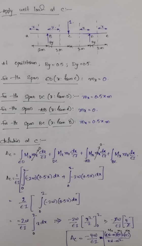
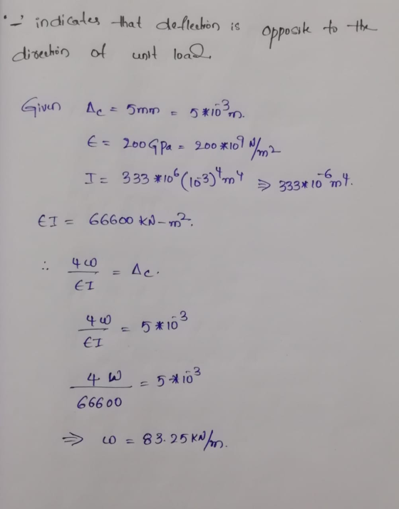
For the beam and loading shown, and knowing that distance a = 2m, determine the maximum value of the distributed load W so the deflection at midpoint C does not exceed 5 mm Use E = 200 GPa and Ix = 333 x 106 mm4.

Homework Answers

Add Answer to:
For the beam and loading shown, and knowing that distance a =
2m, determine the maximum...
For the beam and loading shown, determine the vertical reaction at the support located at A....
 For the beam and loading shown, determine the vertical reaction
at the support located at A. The distributed load w = 10kN/m, and
the beam W 310 x 52 has a moment of inertia Ix = 119 x
106 mm4 and modulus of elasticity E = 200
GPa
ЕВ с 2 m- 4 m
For the beam and loading shown, determine the vertical reaction
at the support located at A. The distributed load w = 10kN/m, and
the beam W 310 x 52 has a moment of inertia Ix = 119 x
106 mm4 and modulus of elasticity E = 200
GPa
ЕВ с 2 m- 4 m
Question 4 (25 marks) For the beam and loading shown in Figure 4, knowing that a...
 Question 4 (25 marks) For the beam and loading shown in Figure 4, knowing that a GPa, determine (a) the slope at support A, (b) the deflection at point C. (using integration method) 2m, w 50KN/m and E 200 80 w 20 60 Unit: mm A 10 60 В а 20 6 m 80 (a) Beam loading (b) Cross section Figure 4
Question 3 For the simply supported steel beam with cross section and loading shown (see Figure...
 Question 3 For the simply supported steel beam with cross section and loading shown (see Figure 3a), knowing that uniformly distributed load w=60 kN/m, Young modulus E = 200 GPa, and yield stress Cyield=200 MPa (in both tension and compression). ул 15 mm w=60 kN/m ... 1 B A 15 mm + 300 mm IC - i 2.5m 1 1 15 mm 7.5m 1 150 mm Figure 3a (a) Check if: the beam is safe with respect to yielding (using...
2. The governing differential equation that relates the deflection y of a beam to the load w ia w...
 2. The governing differential equation that relates the deflection y of a beam to the load w ia where both y and w are are functions of r. In the above equation, E is the modulus of elasticity and I is the moment of inertia of the beam. For the beam and loading shown in the figure, first de m, E = 200 GPa, 1 = 100 × 106 mm4 and uo 100 kN/m and determine the maximum deflection. Note...
Using Finite Element with a minimum of 3 elements (Penalty Approach). For the beam and loading sh...
 Using Finite Element with a minimum of 3 elements
(Penalty Approach). For the beam and loading shown,
determine (a) the slope at the end A, (b) the deflection at point
C. Use E= 200 GPa And I = 6.83 x 106 mm4
or the beam and loading shown, determine (a) the slope at end A, (6) the deflection at point C. Use E 200 GPa and I -6.83 x 10+6mm4 Use FEM with a minimum of 3 elements(Penalty Approach). 20...
Using Finite Element with a minimum of 3 elements
(Penalty Approach). For the beam and loading shown,
determine (a) the slope at the end A, (b) the deflection at point
C. Use E= 200 GPa And I = 6.83 x 106 mm4
or the beam and loading shown, determine (a) the slope at end A, (6) the deflection at point C. Use E 200 GPa and I -6.83 x 10+6mm4 Use FEM with a minimum of 3 elements(Penalty Approach). 20...
The simply supported beam consists of a W410 × 60 structural steel wide-flange shape [E =...
 The simply supported beam consists of a W410 × 60 structural
steel wide-flange shape [E = 200 GPa; I = 216 ×
106 mm4]. For the loading shown, determine
the beam deflection at point C.
Assume P = 53 kN, w = 91 kN/m,
LAB = LBC = 1.7 m,
LDE = LCD=1.8 m,
MA = 197 kN-m.
200 GPa; I 216 x 100 mm ]. For the loading shown, determine the beam The simply supported beam consists of a...
The simply supported beam consists of a W410 × 60 structural
steel wide-flange shape [E = 200 GPa; I = 216 ×
106 mm4]. For the loading shown, determine
the beam deflection at point C.
Assume P = 53 kN, w = 91 kN/m,
LAB = LBC = 1.7 m,
LDE = LCD=1.8 m,
MA = 197 kN-m.
200 GPa; I 216 x 100 mm ]. For the loading shown, determine the beam The simply supported beam consists of a...
5. For the beam and loading shown, and wo-1000 N/m, L-3 m, and E-200 GPa. Determine...
 5. For the beam and loading shown, and wo-1000 N/m, L-3 m, and E-200 GPa. Determine (a) the equation of the elastic curve, and (b) the maximum deflection. Wo 8 mm 300 DT 8 mm ト150mm 〒8mm 150 mm
P10.047 (Multistep) The simply supported beam shown in the figure consists of a W410 x 60...
 P10.047 (Multistep) The simply supported beam shown in the figure consists of a W410 x 60 structural steel wide-flange shape [E = 200 GPa; I = 216 x 100 mm"]. For the loading shown, determine the beam deflection at point B. Assume P = 88 kN, w = 94 kN/m, M = 162 kNm, and d= 1.5 m. .PL IIIIIIIIIIIII Part 3 Neglect the concentrated moment M and the concentrated load P and determine the deflection at B due to...
For the cantilever beam and loading shown, use the method of superposition to determine (a) the...
 For the cantilever beam and loading shown, use the method of superposition to determine (a) the slope at point A, (b) the deflection at point A. Use E 200 GPa. Hint: Use the expression found in Problem 1 for the tri angular load. 120 kN/m W360 × 64 20 kN 2.1 m
The simply supported beam consists of a W410 × 60 structural steel wide-flange shape [E = 200 GPa; I = 216 × 106 mm4]. F...
 The simply supported beam consists of a W410 × 60 structural
steel wide-flange shape [E = 200 GPa; I = 216 ×
106 mm4]. For the loading shown, determine
the beam deflection at point C.
Assume P = 72 kN, w = 60 kN/m,
LAB = LBC = 1.4 m,
LDE = LCD=1.4 m,
MA = 167 kN-m.
P10.048 Not Correct 216 x 106 mm41. For the loading shown, determine the beam deflection at point C The simply supported beam...
The simply supported beam consists of a W410 × 60 structural
steel wide-flange shape [E = 200 GPa; I = 216 ×
106 mm4]. For the loading shown, determine
the beam deflection at point C.
Assume P = 72 kN, w = 60 kN/m,
LAB = LBC = 1.4 m,
LDE = LCD=1.4 m,
MA = 167 kN-m.
P10.048 Not Correct 216 x 106 mm41. For the loading shown, determine the beam deflection at point C The simply supported beam...
 For the beam and loading shown, determine the vertical reaction
at the support located at A. The distributed load w = 10kN/m, and
the beam W 310 x 52 has a moment of inertia Ix = 119 x
106 mm4 and modulus of elasticity E = 200
GPa
ЕВ с 2 m- 4 m
For the beam and loading shown, determine the vertical reaction
at the support located at A. The distributed load w = 10kN/m, and
the beam W 310 x 52 has a moment of inertia Ix = 119 x
106 mm4 and modulus of elasticity E = 200
GPa
ЕВ с 2 m- 4 m
 Question 4 (25 marks) For the beam and loading shown in Figure 4, knowing that a GPa, determine (a) the slope at support A, (b) the deflection at point C. (using integration method) 2m, w 50KN/m and E 200 80 w 20 60 Unit: mm A 10 60 В а 20 6 m 80 (a) Beam loading (b) Cross section Figure 4
 Question 3 For the simply supported steel beam with cross section and loading shown (see Figure 3a), knowing that uniformly distributed load w=60 kN/m, Young modulus E = 200 GPa, and yield stress Cyield=200 MPa (in both tension and compression). ул 15 mm w=60 kN/m ... 1 B A 15 mm + 300 mm IC - i 2.5m 1 1 15 mm 7.5m 1 150 mm Figure 3a (a) Check if: the beam is safe with respect to yielding (using...
 2. The governing differential equation that relates the deflection y of a beam to the load w ia where both y and w are are functions of r. In the above equation, E is the modulus of elasticity and I is the moment of inertia of the beam. For the beam and loading shown in the figure, first de m, E = 200 GPa, 1 = 100 × 106 mm4 and uo 100 kN/m and determine the maximum deflection. Note...
 Using Finite Element with a minimum of 3 elements
(Penalty Approach). For the beam and loading shown,
determine (a) the slope at the end A, (b) the deflection at point
C. Use E= 200 GPa And I = 6.83 x 106 mm4
or the beam and loading shown, determine (a) the slope at end A, (6) the deflection at point C. Use E 200 GPa and I -6.83 x 10+6mm4 Use FEM with a minimum of 3 elements(Penalty Approach). 20...
Using Finite Element with a minimum of 3 elements
(Penalty Approach). For the beam and loading shown,
determine (a) the slope at the end A, (b) the deflection at point
C. Use E= 200 GPa And I = 6.83 x 106 mm4
or the beam and loading shown, determine (a) the slope at end A, (6) the deflection at point C. Use E 200 GPa and I -6.83 x 10+6mm4 Use FEM with a minimum of 3 elements(Penalty Approach). 20...
 The simply supported beam consists of a W410 × 60 structural
steel wide-flange shape [E = 200 GPa; I = 216 ×
106 mm4]. For the loading shown, determine
the beam deflection at point C.
Assume P = 53 kN, w = 91 kN/m,
LAB = LBC = 1.7 m,
LDE = LCD=1.8 m,
MA = 197 kN-m.
200 GPa; I 216 x 100 mm ]. For the loading shown, determine the beam The simply supported beam consists of a...
The simply supported beam consists of a W410 × 60 structural
steel wide-flange shape [E = 200 GPa; I = 216 ×
106 mm4]. For the loading shown, determine
the beam deflection at point C.
Assume P = 53 kN, w = 91 kN/m,
LAB = LBC = 1.7 m,
LDE = LCD=1.8 m,
MA = 197 kN-m.
200 GPa; I 216 x 100 mm ]. For the loading shown, determine the beam The simply supported beam consists of a...
 5. For the beam and loading shown, and wo-1000 N/m, L-3 m, and E-200 GPa. Determine (a) the equation of the elastic curve, and (b) the maximum deflection. Wo 8 mm 300 DT 8 mm ト150mm 〒8mm 150 mm
 P10.047 (Multistep) The simply supported beam shown in the figure consists of a W410 x 60 structural steel wide-flange shape [E = 200 GPa; I = 216 x 100 mm"]. For the loading shown, determine the beam deflection at point B. Assume P = 88 kN, w = 94 kN/m, M = 162 kNm, and d= 1.5 m. .PL IIIIIIIIIIIII Part 3 Neglect the concentrated moment M and the concentrated load P and determine the deflection at B due to...
 For the cantilever beam and loading shown, use the method of superposition to determine (a) the slope at point A, (b) the deflection at point A. Use E 200 GPa. Hint: Use the expression found in Problem 1 for the tri angular load. 120 kN/m W360 × 64 20 kN 2.1 m
 The simply supported beam consists of a W410 × 60 structural
steel wide-flange shape [E = 200 GPa; I = 216 ×
106 mm4]. For the loading shown, determine
the beam deflection at point C.
Assume P = 72 kN, w = 60 kN/m,
LAB = LBC = 1.4 m,
LDE = LCD=1.4 m,
MA = 167 kN-m.
P10.048 Not Correct 216 x 106 mm41. For the loading shown, determine the beam deflection at point C The simply supported beam...
The simply supported beam consists of a W410 × 60 structural
steel wide-flange shape [E = 200 GPa; I = 216 ×
106 mm4]. For the loading shown, determine
the beam deflection at point C.
Assume P = 72 kN, w = 60 kN/m,
LAB = LBC = 1.4 m,
LDE = LCD=1.4 m,
MA = 167 kN-m.
P10.048 Not Correct 216 x 106 mm41. For the loading shown, determine the beam deflection at point C The simply supported beam...
Most questions answered within 3 hours.
-
An acidic solution containing gold ions is
electrolyzed, producing gaseous oxygen (from water) at the anode...
asked 7 minutes ago -
Assume that the population of Mexico is 128
million and that the population increases 1.01
percentannually....
asked 1 hour ago -
Can someone please help me add appropriate descriptive
comments to each line of code in the...
asked 1 hour ago -
Romeo wishes to throw a bouquet of flowers to Juliet, who is on
a second-story balcony,...
asked 2 hours ago -
Why is QE a controversial monetary policy tool.
A. It may lead to excessive inflation.B. By...
asked 2 hours ago -
Principles of Programming midterm study guide help!
1.)
______ Which of the following would reference the...
asked 1 hour ago -
A finite potential well has depth U0 = 2.78 eV . What is the
penetration distance...
asked 2 hours ago -
1. The bus bars of a power station are in two sections A and B
separated...
asked 2 hours ago -
Fiscal policy is the deliberate manipulation of taxes and
government spending to alter GDP, employment, inflation...
asked 3 hours ago -
evaluating an expression using only one digit and + and - as
operators ....3+5-1+7-5+8
-----------------------
stack...
asked 3 hours ago -
Two concentric current loops lie in the same plane. The smaller
loop has a radius of...
asked 4 hours ago -
1)Which of the following is an
important difference between qualified and nonqualified retirement
plans?
a. Qualified...
asked 4 hours ago