

Homework Answers
ANSWER : 
![and Pterations: (Kelbow = 0.5) aceis (m) slo Re = VD of pipe (x105] (x105) h = fly2 2 Kelbow 294 + 29 9 1 70415 5.35 145 0-0](http://img.homeworklib.com/questions/8077bb90-f9b2-11ea-90ba-ed32f67355a1.png?x-oss-process=image/resize,w_560)

Add Answer to:
Water at 20° flows in pipeline system shown below (Fig. 1) at rate of 32400 Vhr....
Temperature Density °C kg/m3 0 999.82 5 1000.00 10 999.77 15 999.19 20 998.29 25 997.13...
 Temperature Density °C kg/m3 0 999.82 5 1000.00 10 999.77 15 999.19 20 998.29 25 997.13 30 995.71 35 994.08 40 992.25 45 990.22 50 988.02 55 985.65 60 983.13 65 980.45 70 977.63 75 974.68 80 971.60 85 968.39 90 965.06 95 961.62 100 958.05 Dynamic viscosity kg/m.s 0.0017920 0.0015200 0.0013080 0.0011390 0.0010030 0.0008910 0.0007980 0.0007200 0.0006530 0.0005960 0.0005470 0.0005040 0.0004670 0.0004340 0.0004040 0.0003780 0.0003550 0.0003340 0.0003150 0.0002980 0.0002820 Kinematic viscosity mºs x 10-6 1.7923226 1.5200000 1.3083009 1.1399233 1.0047181...
Water at 20° flows in pipeline system shown below (Fig. 1) at rate of 32400 Vhr....
 Water at 20° flows in pipeline system shown below (Fig. 1) at rate of 32400 Vhr. Pipe 1 is 15m long and 0.044 m outer diameter and pipe 2 is 100m long and 0.034m outer diameter. The thickness of both pipes is 2mm. Pipe 1 is a ductile iron uncoated pipe and pipe 2 is ductile iron coated pipe. There are totally 4 elbows in the system (two elbows in each pipe) and the elbows are 90° street elbows. All...
Water at 20° flows in pipeline system shown below (Fig.1) at rate of 32400 1hr. Pipe...
 Water at 20° flows in pipeline system shown below (Fig.1) at rate of 32400 1hr. Pipe 1 is 15m long and 0.044 m outer diameter and pipe 2 is 100m long and 0.034m outer diameter. The thickness of both pipes is 2mm. Pipe 1 is a ductile iron uncoated pipe and pipe 2 is ductile iron coated pipe. There are totally 4 elbows in the system (two elbows in each pipe) and the elbows are 90° street elbows. All pipes...
1.por - + 2 Fit to page ID Page Exercise 1 (15 marks) Water at 20°...
 1.por - + 2 Fit to page ID Page Exercise 1 (15 marks) Water at 20° flows in pipeline system shown below (Fig.1) at rate of 32400 l/hr. Pipe 1 is 15m long and 0.044 m outer diameter and pipe 2 is 100m long and 0.034m outer diameter. The thickness of both pipes is 2mm. Pipe 1 is a ductile iron uncoated pipe and pipe 2 is ductile iron coated pipe. There are totally 4 elbows in the system (two...
6. (25 points) Water at standard atmospheric conditions flows through a 100 m long plastic pipe...
 6. (25 points) Water at standard atmospheric conditions flows through a 100 m long plastic pipe with a circular cross section of diameter D = 0.2 m at an average velocity of 10 cm/s. The flow exits into the atmosphere. The pipe material is smooth and has essentially no roughness. What is the pressure at the pipe entrance if it is horizontal? What is the pressure at the pipe entrance if the elevation increases by 50 cm? A Moody diagram...
Water flows through a pipe at a velocity of 1 m/s. The pipe has a relative roughness of 0.001 and...
 Water flows through a pipe at a velocity of 1 m/s. The pipe has a relative roughness of 0.001 and has a diameter of 100 mm 1. Using the information provided above and in the Moody diagram, drag and drop circle 1 (located below the graph) where the corresponding Reynolds number and relative roughness intersect 2. Drag and drop circle 2 to the point on the y axis at which you would measure the friction factor () v 10-6 m2/s...
2. Water flows at a rate of 60 L/s from a main reservoir to a subsidiary...
 2. Water flows at a rate of 60 L/s from a main reservoir to a subsidiary through a 600 m long, 185 mm diameter asphalted cast iron pipe as shown in the figure. The pipeline contains a gate valve, a globe valve and 4 standard 90° elbows. The entrance and exit are square edged, and all fittings are screwed ends, determine, You need Kinematic viscosity of water, 1 x 10⁻⁶ m/s2 (a) The friction head loss in the pipe, (b)...
1) Consider the schematic diagram below. If the pump supplies 225kW to the water, what flow rate ...
 1) Consider the schematic diagram below. If the pump supplies 225kW to the water, what flow rate will occur in the pipes? Pump 1 has length 450m and diameter 200mm. Pipe Π has length of 450m and diameter of 250mm. Assume a friction factor of f-0.02 for both pipes. gnore all minor losses and the losses in the pipe upstream of the pump. (ans. Q,-0.1 m3/s, Q1-0.175m3/s) RL-90m RL=30m >Pipe Pump Water Pipe II
1) Consider the schematic diagram below....
1) Consider the schematic diagram below. If the pump supplies 225kW to the water, what flow rate will occur in the pipes? Pump 1 has length 450m and diameter 200mm. Pipe Π has length of 450m and diameter of 250mm. Assume a friction factor of f-0.02 for both pipes. gnore all minor losses and the losses in the pipe upstream of the pump. (ans. Q,-0.1 m3/s, Q1-0.175m3/s) RL-90m RL=30m >Pipe Pump Water Pipe II
1) Consider the schematic diagram below....
Problem 3 A pipeline delivers water from Reservoir 1 to Reservoir 2 as shown in the following figure. The water levels at Reservoirs 1 and 2 are 50 ft and 20 ft, respectively. A globe valve is in...
 Problem 3 A pipeline delivers water from Reservoir 1 to Reservoir 2 as shown in the following figure. The water levels at Reservoirs 1 and 2 are 50 ft and 20 ft, respectively. A globe valve is installed in the pipeline with a minor head loss coefficient k 10. The pipe from Reservoir 1 to the globe valve is 1000 ft long and 6 inches in diameter. The pipe from the globe valve to Reservoir 2 is also 1000 ft...
1) Water is flowing through the 50-mm galvanized-iron pipe system shown in the figure. The average...
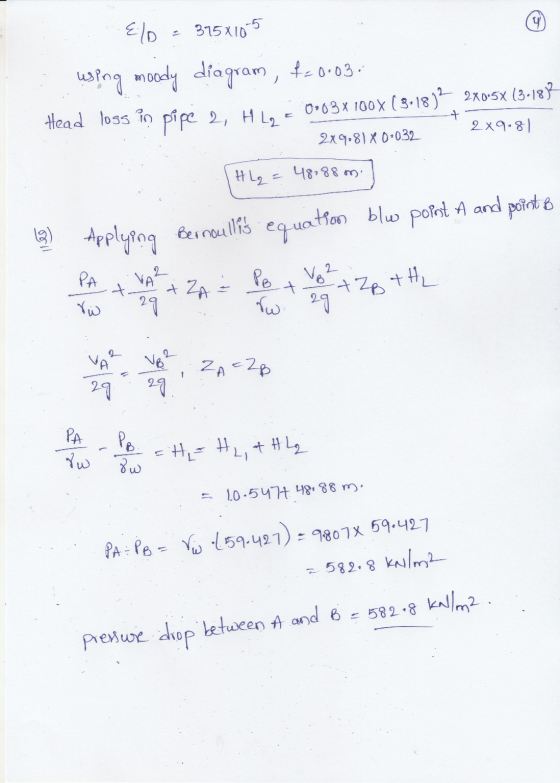
 1) Water is flowing through the 50-mm galvanized-iron pipe system shown in the figure. The average velocity in the pipe is V=3.5 m/s. Assume the temperature is 20°C. a) What is friction loss between Points A and B? b) What is the pressure at Point A, if Point B is a free jet? Use the Moody Diagram to solve. 50 mm 2) For the same conditions in Problem #1, use the "Fully-Rough" equation to determine the friction factor, f. Compare...
 Temperature Density °C kg/m3 0 999.82 5 1000.00 10 999.77 15 999.19 20 998.29 25 997.13 30 995.71 35 994.08 40 992.25 45 990.22 50 988.02 55 985.65 60 983.13 65 980.45 70 977.63 75 974.68 80 971.60 85 968.39 90 965.06 95 961.62 100 958.05 Dynamic viscosity kg/m.s 0.0017920 0.0015200 0.0013080 0.0011390 0.0010030 0.0008910 0.0007980 0.0007200 0.0006530 0.0005960 0.0005470 0.0005040 0.0004670 0.0004340 0.0004040 0.0003780 0.0003550 0.0003340 0.0003150 0.0002980 0.0002820 Kinematic viscosity mºs x 10-6 1.7923226 1.5200000 1.3083009 1.1399233 1.0047181...
 Water at 20° flows in pipeline system shown below (Fig. 1) at rate of 32400 Vhr. Pipe 1 is 15m long and 0.044 m outer diameter and pipe 2 is 100m long and 0.034m outer diameter. The thickness of both pipes is 2mm. Pipe 1 is a ductile iron uncoated pipe and pipe 2 is ductile iron coated pipe. There are totally 4 elbows in the system (two elbows in each pipe) and the elbows are 90° street elbows. All...
 Water at 20° flows in pipeline system shown below (Fig.1) at rate of 32400 1hr. Pipe 1 is 15m long and 0.044 m outer diameter and pipe 2 is 100m long and 0.034m outer diameter. The thickness of both pipes is 2mm. Pipe 1 is a ductile iron uncoated pipe and pipe 2 is ductile iron coated pipe. There are totally 4 elbows in the system (two elbows in each pipe) and the elbows are 90° street elbows. All pipes...
 1.por - + 2 Fit to page ID Page Exercise 1 (15 marks) Water at 20° flows in pipeline system shown below (Fig.1) at rate of 32400 l/hr. Pipe 1 is 15m long and 0.044 m outer diameter and pipe 2 is 100m long and 0.034m outer diameter. The thickness of both pipes is 2mm. Pipe 1 is a ductile iron uncoated pipe and pipe 2 is ductile iron coated pipe. There are totally 4 elbows in the system (two...
 6. (25 points) Water at standard atmospheric conditions flows through a 100 m long plastic pipe with a circular cross section of diameter D = 0.2 m at an average velocity of 10 cm/s. The flow exits into the atmosphere. The pipe material is smooth and has essentially no roughness. What is the pressure at the pipe entrance if it is horizontal? What is the pressure at the pipe entrance if the elevation increases by 50 cm? A Moody diagram...
 Water flows through a pipe at a velocity of 1 m/s. The pipe has a relative roughness of 0.001 and has a diameter of 100 mm 1. Using the information provided above and in the Moody diagram, drag and drop circle 1 (located below the graph) where the corresponding Reynolds number and relative roughness intersect 2. Drag and drop circle 2 to the point on the y axis at which you would measure the friction factor () v 10-6 m2/s...
 2. Water flows at a rate of 60 L/s from a main reservoir to a subsidiary through a 600 m long, 185 mm diameter asphalted cast iron pipe as shown in the figure. The pipeline contains a gate valve, a globe valve and 4 standard 90° elbows. The entrance and exit are square edged, and all fittings are screwed ends, determine, You need Kinematic viscosity of water, 1 x 10⁻⁶ m/s2 (a) The friction head loss in the pipe, (b)...
 1) Consider the schematic diagram below. If the pump supplies 225kW to the water, what flow rate will occur in the pipes? Pump 1 has length 450m and diameter 200mm. Pipe Π has length of 450m and diameter of 250mm. Assume a friction factor of f-0.02 for both pipes. gnore all minor losses and the losses in the pipe upstream of the pump. (ans. Q,-0.1 m3/s, Q1-0.175m3/s) RL-90m RL=30m >Pipe Pump Water Pipe II
1) Consider the schematic diagram below....
1) Consider the schematic diagram below. If the pump supplies 225kW to the water, what flow rate will occur in the pipes? Pump 1 has length 450m and diameter 200mm. Pipe Π has length of 450m and diameter of 250mm. Assume a friction factor of f-0.02 for both pipes. gnore all minor losses and the losses in the pipe upstream of the pump. (ans. Q,-0.1 m3/s, Q1-0.175m3/s) RL-90m RL=30m >Pipe Pump Water Pipe II
1) Consider the schematic diagram below....
 Problem 3 A pipeline delivers water from Reservoir 1 to Reservoir 2 as shown in the following figure. The water levels at Reservoirs 1 and 2 are 50 ft and 20 ft, respectively. A globe valve is installed in the pipeline with a minor head loss coefficient k 10. The pipe from Reservoir 1 to the globe valve is 1000 ft long and 6 inches in diameter. The pipe from the globe valve to Reservoir 2 is also 1000 ft...
 1) Water is flowing through the 50-mm galvanized-iron pipe system shown in the figure. The average velocity in the pipe is V=3.5 m/s. Assume the temperature is 20°C. a) What is friction loss between Points A and B? b) What is the pressure at Point A, if Point B is a free jet? Use the Moody Diagram to solve. 50 mm 2) For the same conditions in Problem #1, use the "Fully-Rough" equation to determine the friction factor, f. Compare...
Most questions answered within 3 hours.
-
Marla’s Massages and More bought a special massage table two
years ago for $9,300. At the...
asked 59 seconds ago -
Suppose you require a peak output voltage of 15.0 V and have
available an AC source...
asked 1 minute ago -
We
conduct A study to estimate the mean age of the population of women
at the...
asked 12 minutes ago -
.13 : Assume that we make an enhancement to a computer that
improves some mode of...
asked 14 minutes ago -
4)
Find the tension in an elevator cable if the 1000 kg elevator is
descending with...
asked 20 minutes ago -
A random sample of 51 newborn babies was taken at the Hospital.
The sample mean was...
asked 18 minutes ago -
Industry standards suggest that 16% of new vehicles require
warranty service within the first year. Jones...
asked 29 minutes ago -
1) Comment of this statement: “A compiler transforms high-level
language statements directly into object codes”.
asked 32 minutes ago -
Calculate the molality, mole-fraction and percent mass of 28.9M
HF at 25 degrees Celcius of the...
asked 41 minutes ago -
A developmental psychologist believes that children raised in
bilingual families will have higher verbal fluency at...
asked 48 minutes ago -
A fast food meal has 5660 kJ of energy. A person uses energy at
a rate...
asked 1 hour ago -
The pKb for a generic amine(R-NH2)) in
aqueous solution is 6.30. What is its pKa?
asked 1 hour ago