
Homework Answers


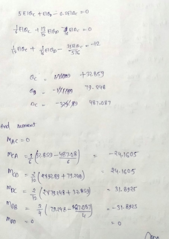
![R4, 65 З.092 12 m) 24лск) в с 31. 8925 um (п D Ио А Ке HA RA Идува 24. 1605 Ав XV— 3]. 82 МАР Ч, 6615 Иn = 7.97 335 НА — Ч,62](http://img.homeworklib.com/questions/ca51ca10-fb79-11ea-a4a1-d1b63ff3296d.png?x-oss-process=image/resize,w_560)

Add Answer to:
12 D 4m In the frame system given in the figure, a. Mesnet reactions, b. Bending...
3 tim 20+ D 21 The single span and single storey frame system and moment diagram...
 3 tim 20+ D 21 The single span and single storey frame system and moment diagram in the figure are given together. a. Calculate the horizontal displacement (AXC) at the C point. b. Calculate the rotation displacement (ØD) at point D. In displacement accounts, deformations consisting of Q and N will be neglected. EI=10000tm2 10m 131 311 L. B 10m -58,75 C 21.25 -58,75 21.25 D B -50.63 69,37
48 KN/m 1- Shear Force Diagram: с 72 KN 2m 4m 2m 54 KN D 8m...
 48 KN/m 1- Shear Force Diagram: с 72 KN 2m 4m 2m 54 KN D 8m D 4m 4m B B Steps of Calculation: 5m 5m 2- Moment Diagram: a) Draw the V and M diagrams of the three-hinged-frame. b) Calculate the value of the horizontal displacement of C point. EI: Constant D a) Determination The Values of The Reaction Force: B Steps of Calculation: b) Calculation The Value of Displacement: Belge sonu
To G 3m E, F and G points are hinged in the frame system in the...
 To G 3m E, F and G points are hinged in the frame system in the figure. The cross sections of all elements are the same. Calculate the support reactions for the given external loading. NOTE: In the calculations, deformations consisting of Q and N will be neglected in all elements. E F 5m t/m 10+ D 5m ar 4m 8
15 marks Question 3 Consider the frame shown in Figure Q3 for which all elements have constant stiffness EL. Implement the flexibility method by removing the vertical support at A to create a static...
 15 marks Question 3 Consider the frame shown in Figure Q3 for which all elements have constant stiffness EL. Implement the flexibility method by removing the vertical support at A to create a statically determinate system. The Volume Integral Table is found on page 8 of this examination paper Find the reactions at A and D considering that node C is equidistant to nodes D (a) and B [12 marks] (b) Draw the bending moment diagram for the frame. 13...
4 k B Elpc 12 ft ElAB 24 ft The statically determinate rigidly connected frame has a pin support at point A and a roller support at point C. The frame is subjected to a point load at point B. The...
 4 k B Elpc 12 ft ElAB 24 ft The statically determinate rigidly connected frame has a pin support at point A and a roller support at point C. The frame is subjected to a point load at point B. The frame is rigidly con- nected at point B. If the bending stiffness of column AB is 40,000 k-ft? and the bending stiffness for beam BC is 60,000 k-ft, find: 1. (5%) The bending moment diagram for the frame. Show...
Question 1) (L.0.6.1-4): Using the force method, draw the bending moment, shear force and axial force...
 Question 1) (L.0.6.1-4): Using the force method, draw the bending moment, shear force and axial force diagrams for the structure shown in Figure 1. Effects of shear and axial forces on deformation are neglected. qa? B 2a Figure 1. Question 2) (L.0.7.1-4): Using the displacement method, draw the bending moment diagram for the structure shown in Figure 2. Effects of axial and shear forces on deformation are neglected. 2qa? q qa a/2 a/2 a a/2 a/2 f + Figure 2.
CE 160 Problem 1(15% 4 k B 12 ft AR 24 ft The statically determinate rigidly connected frame has a pin support at point A and a roller support at point C. The frame is subjected to a point load a...
 CE 160 Problem 1(15% 4 k B 12 ft AR 24 ft The statically determinate rigidly connected frame has a pin support at point A and a roller support at point C. The frame is subjected to a point load at point B. The frame is rigidly con- nected at point B. If the bending stiffness of column AB is 40,000 k-ft and the bending stiffness for beam BC is 60,000 k-ft, find: I. (596) The bending moment diagram for...
A two-dimensional two-pinned portal frame ABCDE is pinned to rigid supports at positions A and E,...
 A two-dimensional two-pinned portal frame ABCDE is pinned to rigid supports at positions A and E, and a concentrated couple of 350 kNm acting clockwise is applied at C as shown in Figure Q3. All members of the portal frame are made from the same steel section. 350 kNm 6 m EI CONSTANT FOR ALL MEMBERS 6 m 4 m Fgure Q3 Determine, using methods incorporating strain energy where appropriate. the magnitude and direction of the vertical and horizontal reactions...
Question 2: A simply supported beam under loading as shown in Figure 1: 1. Draw the influence lines of the bending moment and shear force at point C (L/4) Using the influence lines to determine t...
 Question 2: A simply supported beam under loading as shown in Figure 1: 1. Draw the influence lines of the bending moment and shear force at point C (L/4) Using the influence lines to determine the bending moment and shear force at section C due to the loading as shown in the figure. 2. 3. There is a distributed live load (w#2.5kN/m) which can vary the location along the beam. Determine the location of the live loads which create the...
Q1. The frame shown has two pin supports at points A and B. The horizontal reaction...
 Q1. The frame shown has two pin supports at points A and B. The horizontal reaction at B is -1.83kN (1.83kN to the left). Calculate the remaining reactions for the frame and draw the bending moment diagram, calculating and marking all local maximum moments. Also sketch the deflected shape, noting any points of inflexion 2kN 5 m 1.5 m 0.75 kN/m 4m Deflected BMD Shape
 3 tim 20+ D 21 The single span and single storey frame system and moment diagram in the figure are given together. a. Calculate the horizontal displacement (AXC) at the C point. b. Calculate the rotation displacement (ØD) at point D. In displacement accounts, deformations consisting of Q and N will be neglected. EI=10000tm2 10m 131 311 L. B 10m -58,75 C 21.25 -58,75 21.25 D B -50.63 69,37
 48 KN/m 1- Shear Force Diagram: с 72 KN 2m 4m 2m 54 KN D 8m D 4m 4m B B Steps of Calculation: 5m 5m 2- Moment Diagram: a) Draw the V and M diagrams of the three-hinged-frame. b) Calculate the value of the horizontal displacement of C point. EI: Constant D a) Determination The Values of The Reaction Force: B Steps of Calculation: b) Calculation The Value of Displacement: Belge sonu
 To G 3m E, F and G points are hinged in the frame system in the figure. The cross sections of all elements are the same. Calculate the support reactions for the given external loading. NOTE: In the calculations, deformations consisting of Q and N will be neglected in all elements. E F 5m t/m 10+ D 5m ar 4m 8
 15 marks Question 3 Consider the frame shown in Figure Q3 for which all elements have constant stiffness EL. Implement the flexibility method by removing the vertical support at A to create a statically determinate system. The Volume Integral Table is found on page 8 of this examination paper Find the reactions at A and D considering that node C is equidistant to nodes D (a) and B [12 marks] (b) Draw the bending moment diagram for the frame. 13...
 4 k B Elpc 12 ft ElAB 24 ft The statically determinate rigidly connected frame has a pin support at point A and a roller support at point C. The frame is subjected to a point load at point B. The frame is rigidly con- nected at point B. If the bending stiffness of column AB is 40,000 k-ft? and the bending stiffness for beam BC is 60,000 k-ft, find: 1. (5%) The bending moment diagram for the frame. Show...
 Question 1) (L.0.6.1-4): Using the force method, draw the bending moment, shear force and axial force diagrams for the structure shown in Figure 1. Effects of shear and axial forces on deformation are neglected. qa? B 2a Figure 1. Question 2) (L.0.7.1-4): Using the displacement method, draw the bending moment diagram for the structure shown in Figure 2. Effects of axial and shear forces on deformation are neglected. 2qa? q qa a/2 a/2 a a/2 a/2 f + Figure 2.
 CE 160 Problem 1(15% 4 k B 12 ft AR 24 ft The statically determinate rigidly connected frame has a pin support at point A and a roller support at point C. The frame is subjected to a point load at point B. The frame is rigidly con- nected at point B. If the bending stiffness of column AB is 40,000 k-ft and the bending stiffness for beam BC is 60,000 k-ft, find: I. (596) The bending moment diagram for...
 A two-dimensional two-pinned portal frame ABCDE is pinned to rigid supports at positions A and E, and a concentrated couple of 350 kNm acting clockwise is applied at C as shown in Figure Q3. All members of the portal frame are made from the same steel section. 350 kNm 6 m EI CONSTANT FOR ALL MEMBERS 6 m 4 m Fgure Q3 Determine, using methods incorporating strain energy where appropriate. the magnitude and direction of the vertical and horizontal reactions...
 Question 2: A simply supported beam under loading as shown in Figure 1: 1. Draw the influence lines of the bending moment and shear force at point C (L/4) Using the influence lines to determine the bending moment and shear force at section C due to the loading as shown in the figure. 2. 3. There is a distributed live load (w#2.5kN/m) which can vary the location along the beam. Determine the location of the live loads which create the...
 Q1. The frame shown has two pin supports at points A and B. The horizontal reaction at B is -1.83kN (1.83kN to the left). Calculate the remaining reactions for the frame and draw the bending moment diagram, calculating and marking all local maximum moments. Also sketch the deflected shape, noting any points of inflexion 2kN 5 m 1.5 m 0.75 kN/m 4m Deflected BMD Shape
Most questions answered within 3 hours.
-
Do you think companies should not go for long term debt in their
capital structure to...
asked 6 minutes ago -
I create an address book where the user enters the name, phone
and email in the...
asked 12 minutes ago -
The production capacity for acrylonitrile
(C3H3N) in the United States exceeds 2
million pounds per year....
asked 20 minutes ago -
explain and comment out your answer
43. How many address lines are required to address a...
asked 26 minutes ago -
A sample of 45 observations is selected from a normal
population. The sample mean is 49,...
asked 41 minutes ago -
A construction company is planning to bid on a building
contract. The bid costs the company...
asked 38 minutes ago -
A firm operating in a purely competitive environment is faced
with a market price of $250....
asked 45 minutes ago -
•Let’s say someone claims the average population size is
600 feet squared and the housing authority...
asked 53 minutes ago -
Cynaide is a deadly poison that blocks the last step in the
electron transport chain of...
asked 57 minutes ago -
Your friend tells you that there is a vending machine on campus
that dispenses M&M packs...
asked 1 hour ago -
What advantages are there to using piperidine rather than
hydroxide as a base?
asked 1 hour ago -
7. The life of a Freeze Breeze electric fan is normally
distributed with a mean 4...
asked 1 hour ago