
Homework Answers

Add Answer to:
In the figure, the battery has an emf of 12.0 V, the inductance is 2.81mH and...
3. In the figure, the battery has an emf of 12.0 V, the inductance is 2.81mH...
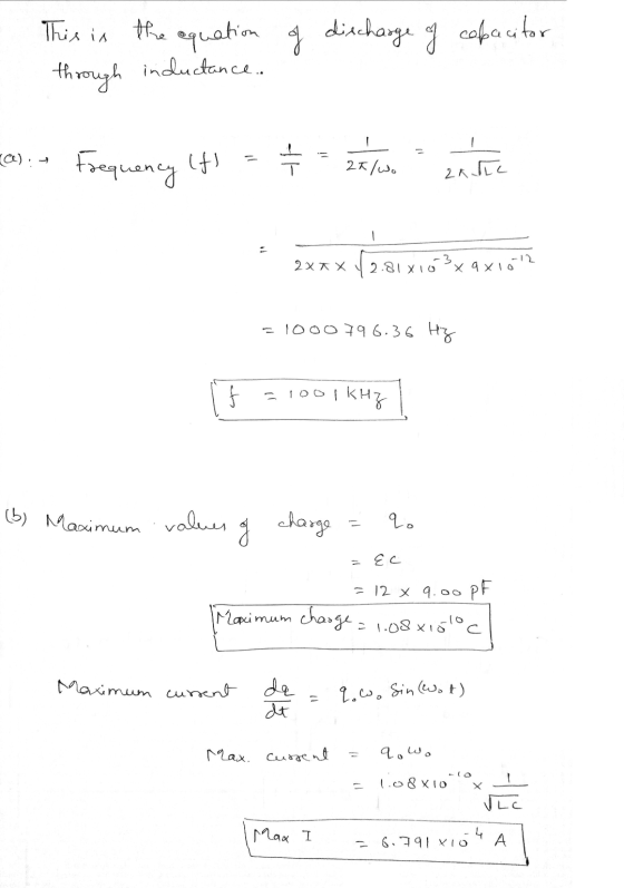
 3. In the figure, the battery has an emf of 12.0 V, the inductance is 2.81mH and the capacitance is 9.00 pF. The switch has been set to position a for a long time so that the capacitor is charged. The switch is then thrown to position b, removing the battery from the circuit and connecting the capacitor directly across the inductor. a. Find the frequency of oscillation of the circuit. b. What are the maximum values of charge on...
In the circuit of the figure below, the battery emf E is 50 V, the resistance...
 In the circuit of the figure below, the battery emf E is 50 V, the resistance R is 210 Q, and the capacitance C is 0.500 pF. The switch S is closed for a long time interval, and zero potential difference is measured across the capacitor. After the switch is opened, the potential difference across the capacitor reaches a maximum value of 150 V. What is the value of the inductance? Н С
In the circuit of the figure below, the battery emf e m f is 60 V,...
 In the circuit of the figure
below, the battery emf e m f is 60 V, the resistance R is 150 Ω,
and the capacitance C is 0.500 µF. The switch S is closed for a
long time interval, and zero potential difference is measured
across the capacitor. After the switch is opened, the potential
difference across the capacitor reaches a maximum value of 150 V.
What is the value of the inductance?
In the circuit of the figure below,...
In the circuit of the figure
below, the battery emf e m f is 60 V, the resistance R is 150 Ω,
and the capacitance C is 0.500 µF. The switch S is closed for a
long time interval, and zero potential difference is measured
across the capacitor. After the switch is opened, the potential
difference across the capacitor reaches a maximum value of 150 V.
What is the value of the inductance?
In the circuit of the figure below,...
What is the Kirchhoff's junction rule equation for this junction? A 10-V-emf battery is connected in...
 What is the Kirchhoff's junction rule equation for this junction? A 10-V-emf battery is connected in series with the following: a 2-mu F capacitor, a 2-Ohm resistor, an ammeter, and a switch, initially open; a voltmeter is connected in parallel across the capacitor. After the switch has been closed for a relatively long period (several seconds, say), what are the current and capacitor voltage readings, respectively? A resistor, inductor, battery, and switch are all hooked up in series. Draw a...
A battery with emf Eemf, switch, inductor L and capacitor C are connected in series. Initially...
 A battery with emf Eemf, switch, inductor L and capacitor C are connected in series. Initially the switch is open and capacitor is not charged. Find the maximum current in the circuit after the switch has been closed.
The switch in the figure below is connected to position a for a long time interval....
 The switch in the figure below is connected to position a for a long time interval. At t = 0, the switch is thrown to position b. After this time, what are the following? (Let C = 1.50 μF) 10.0 Ω a b0.100 H 12.0 (a) the frequency of oscillation of the LC circuit Hz (b) the maximum charge that appears on the capacitor με ur (c) the maximum current in the inductor MA (d) the total energy the circuit...
In the figure, R - 12 A, C 8 MF, and 2 - 3 m, and...
 In the figure, R - 12 A, C 8 MF, and 2 - 3 m, and the ideal battery has emf - 32 V. The switch is kept in position a for a long time and then thrown to position b. What are w HE R b HE С L 2000 (a) the maximum charge in the capacitor plates? In the figure, R = 122, C-8 and 2 - 3 m, and the ideal battery has ent - 32 V....
Problem 4:Consider a circuit with two switches, one ideal battery, one resistor, one capacitor and one...
 Problem 4:Consider a circuit with two switches, one ideal battery, one resistor, one capacitor and one inductor. The circuit is drawn below with both switches open: R-14.00 C ; 6.20 uF, and L 54.0 mH, and the ideal battery has emf ξ . 34.0 V. At t-o, both switches are open and the charge on the capacitor is qlt-0) (a) The switch is put at position "a". Compute the charge, oft-S us), on the capacitor after 5.00 microseconds (5x10 sec)...
2. An ideal inductor with inductance L and an ideal capacitor with capacitance C are connected...
 2. An ideal inductor with inductance L and an ideal capacitor with capacitance C are connected in series with a battery with voltage and a switch. Att 0 the switch is closed. In this scenario, the charge on the capacitor will oscillate sinusoidally but will have a DC offset. It can be expressed in general using three parameters (Ao, Ai, and A2) with the following. q(t) AA cos(ut)A2 sin(ut) where wis the natural frequency of the circuit. Note also that...
Part 1 An LC circuit is shown in the figure below. The 32 pF capacitor is...
 Part 1
An LC circuit is shown in the figure below. The 32 pF capacitor
is initially charged by the 10 V battery when S is at position a.
Then S is thrown to position b so that the capacitor is shorted
across the 12 mH inductor
What is the maximum value for the oscillating current assuming
no resistance in the circuit? Answer in units of A.
Part 2
What is the maximum energy stored in the magnetic field of...
Part 1
An LC circuit is shown in the figure below. The 32 pF capacitor
is initially charged by the 10 V battery when S is at position a.
Then S is thrown to position b so that the capacitor is shorted
across the 12 mH inductor
What is the maximum value for the oscillating current assuming
no resistance in the circuit? Answer in units of A.
Part 2
What is the maximum energy stored in the magnetic field of...
 3. In the figure, the battery has an emf of 12.0 V, the inductance is 2.81mH and the capacitance is 9.00 pF. The switch has been set to position a for a long time so that the capacitor is charged. The switch is then thrown to position b, removing the battery from the circuit and connecting the capacitor directly across the inductor. a. Find the frequency of oscillation of the circuit. b. What are the maximum values of charge on...
 In the circuit of the figure below, the battery emf E is 50 V, the resistance R is 210 Q, and the capacitance C is 0.500 pF. The switch S is closed for a long time interval, and zero potential difference is measured across the capacitor. After the switch is opened, the potential difference across the capacitor reaches a maximum value of 150 V. What is the value of the inductance? Н С
 In the circuit of the figure
below, the battery emf e m f is 60 V, the resistance R is 150 Ω,
and the capacitance C is 0.500 µF. The switch S is closed for a
long time interval, and zero potential difference is measured
across the capacitor. After the switch is opened, the potential
difference across the capacitor reaches a maximum value of 150 V.
What is the value of the inductance?
In the circuit of the figure below,...
In the circuit of the figure
below, the battery emf e m f is 60 V, the resistance R is 150 Ω,
and the capacitance C is 0.500 µF. The switch S is closed for a
long time interval, and zero potential difference is measured
across the capacitor. After the switch is opened, the potential
difference across the capacitor reaches a maximum value of 150 V.
What is the value of the inductance?
In the circuit of the figure below,...
 What is the Kirchhoff's junction rule equation for this junction? A 10-V-emf battery is connected in series with the following: a 2-mu F capacitor, a 2-Ohm resistor, an ammeter, and a switch, initially open; a voltmeter is connected in parallel across the capacitor. After the switch has been closed for a relatively long period (several seconds, say), what are the current and capacitor voltage readings, respectively? A resistor, inductor, battery, and switch are all hooked up in series. Draw a...
 A battery with emf Eemf, switch, inductor L and capacitor C are connected in series. Initially the switch is open and capacitor is not charged. Find the maximum current in the circuit after the switch has been closed.
 The switch in the figure below is connected to position a for a long time interval. At t = 0, the switch is thrown to position b. After this time, what are the following? (Let C = 1.50 μF) 10.0 Ω a b0.100 H 12.0 (a) the frequency of oscillation of the LC circuit Hz (b) the maximum charge that appears on the capacitor με ur (c) the maximum current in the inductor MA (d) the total energy the circuit...
 In the figure, R - 12 A, C 8 MF, and 2 - 3 m, and the ideal battery has emf - 32 V. The switch is kept in position a for a long time and then thrown to position b. What are w HE R b HE С L 2000 (a) the maximum charge in the capacitor plates? In the figure, R = 122, C-8 and 2 - 3 m, and the ideal battery has ent - 32 V....
 Problem 4:Consider a circuit with two switches, one ideal battery, one resistor, one capacitor and one inductor. The circuit is drawn below with both switches open: R-14.00 C ; 6.20 uF, and L 54.0 mH, and the ideal battery has emf ξ . 34.0 V. At t-o, both switches are open and the charge on the capacitor is qlt-0) (a) The switch is put at position "a". Compute the charge, oft-S us), on the capacitor after 5.00 microseconds (5x10 sec)...
 2. An ideal inductor with inductance L and an ideal capacitor with capacitance C are connected in series with a battery with voltage and a switch. Att 0 the switch is closed. In this scenario, the charge on the capacitor will oscillate sinusoidally but will have a DC offset. It can be expressed in general using three parameters (Ao, Ai, and A2) with the following. q(t) AA cos(ut)A2 sin(ut) where wis the natural frequency of the circuit. Note also that...
 Part 1
An LC circuit is shown in the figure below. The 32 pF capacitor
is initially charged by the 10 V battery when S is at position a.
Then S is thrown to position b so that the capacitor is shorted
across the 12 mH inductor
What is the maximum value for the oscillating current assuming
no resistance in the circuit? Answer in units of A.
Part 2
What is the maximum energy stored in the magnetic field of...
Part 1
An LC circuit is shown in the figure below. The 32 pF capacitor
is initially charged by the 10 V battery when S is at position a.
Then S is thrown to position b so that the capacitor is shorted
across the 12 mH inductor
What is the maximum value for the oscillating current assuming
no resistance in the circuit? Answer in units of A.
Part 2
What is the maximum energy stored in the magnetic field of...
Most questions answered within 3 hours.
-
Accent Software faces the following conditions. All of these
support Accent’s use of a market-penetration pricing...
asked 54 minutes ago -
A mathematically inclined friend emails you the following
instructions: "Meet me in the cafeteria the first...
asked 56 minutes ago -
A monopoly sells in two countries . The demand curves in the two
countries are p1...
asked 1 hour ago -
A .15kg rubber ball is bounced off a wall. Before hitting the
wall, the ball moves...
asked 2 hours ago -
A manufacturing company preparing to build a new plant is
considering three potential locations for it....
asked 2 hours ago -
B. If compound Y has approximately the same values of solubility
in toluene as compound X,...
asked 3 hours ago -
Oscar Inc. has inventory in Japan valued at 39,051,000 Yen one
year ago. One year ago...
asked 3 hours ago -
If Canada suffered from "fundamental disequilibrium," and its
government choose not to devalue its currency, a...
asked 3 hours ago -
4. How many input & output Key Value Pairs are passed into,
and emitted out of...
asked 3 hours ago -
Why would your heart not function well if constructed of
skeletal muscle? What is the particular...
asked 3 hours ago -
Please respond to this essay question in full essay form for
Chemistry 1102 Organic and Biochemistry:...
asked 3 hours ago -
Determine the head loss and velocity of flow in a water supply main
of 15.0 cm...
asked 3 hours ago