Part II: Problem 5 (15 points) Draw the shear and moment diagrams for the beam and determine the maximum shear and the maximum moment.
Homework Answers


Add Answer to:
Part II: Problem 5 (15 points) Draw the shear and moment
diagrams for the beam and...
answer correctly and all parts plz. Thank you :) Freeman Part II: Problem 5 (15 points)...
 answer correctly and all parts plz. Thank you :)
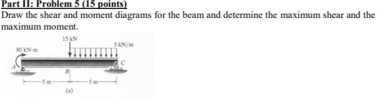
Freeman Part II: Problem 5 (15 points) Draw the shear and moment diagrams for the beam and determine the maximum shear and the maximum moment. 15 kN 5 kN/m 80 kNm B -5 m 5 m (a)
answer correctly and all parts plz. Thank you :)
Freeman Part II: Problem 5 (15 points) Draw the shear and moment diagrams for the beam and determine the maximum shear and the maximum moment. 15 kN 5 kN/m 80 kNm B -5 m 5 m (a)
Draw the shear and moment diagrams for the beam and determine the maximum shear and the...
 Draw the shear and moment diagrams for the beam and determine the maximum shear and the maximum moment. 15 kN 5 kN/m 80 kN.m B Sm 5 m
Draw the shear and moment diagrams for the loaded beam. After you have the diagrams, answer...
 Draw the shear and moment diagrams for the loaded beam. After
you have the diagrams, answer the questions as a check on your
work.
Question 7 Draw the shear and moment diagrams for the loaded beam. After you have the diagrams, answer the questions as a check on your work. 9 KN 7 KN 6 kN/m 4 kN/m e B- ham tomt9m— 5m Questions: When x = 2.3 m, V = KNm When x = 8.6 m, V = kNm...
Draw the shear and moment diagrams for the loaded beam. After
you have the diagrams, answer the questions as a check on your
work.
Question 7 Draw the shear and moment diagrams for the loaded beam. After you have the diagrams, answer the questions as a check on your work. 9 KN 7 KN 6 kN/m 4 kN/m e B- ham tomt9m— 5m Questions: When x = 2.3 m, V = KNm When x = 8.6 m, V = kNm...
Draw the shear and moment diagrams for the loaded beam. After you have the diagrams, answer...
 Draw the shear and moment diagrams for the loaded beam. After you have the diagrams, answer the questions as a check on your work. 6 KN 5 kN/m 6 kN.m La mtu2m + 2m + 2m- 3 m 3m + +3m- 3m Questions: When x = 0.5 m, V = kNm When x = 3.2 m, V = kN.m When x = 6.0 m, V = kN.m When x = 8.2 m, V = kN.m The maximum (absolute value) shear...
4. For the beam and loading shown, draw the shear force and bending moment diagrams and...
 4. For the beam and loading shown, draw the shear force and bending moment diagrams and determine the maximum bending and shear force and their locations. 20 KN 40 KN B D 250 mm |--2.5 m- 3m-4-2 m 80 mm 5. For the beam and loading shown, draw the shear force and bending moment diagrams and determine the maximum bending and shear force and their locations. 50 KN
Draw the shear and moment diagrams for the loaded beam. After you have the diagrams, answer...
 Draw the shear and moment
diagrams for the loaded beam. After you have the diagrams, answer
the questions in order to gain confidence in your plots.
Draw the shear and moment diagrams for the loaded beam. After you have the diagrams, answer the questions in order to gain confidence in your plots. 2 kN 11 kN 5 kNm +3m +4m + 6m — +3m 8 KN Questions: When x = 2.1 m, V = KN.m When x = 5.7 m,...
Draw the shear and moment
diagrams for the loaded beam. After you have the diagrams, answer
the questions in order to gain confidence in your plots.
Draw the shear and moment diagrams for the loaded beam. After you have the diagrams, answer the questions in order to gain confidence in your plots. 2 kN 11 kN 5 kNm +3m +4m + 6m — +3m 8 KN Questions: When x = 2.1 m, V = KN.m When x = 5.7 m,...
For the beam shown, draw the shear and bending moment diagrams and determine the magnitude and...
 For the beam shown, draw the shear and bending moment diagrams and determine the magnitude and location of the maximum absolute values of bending moment knowing that a) M 0, b) M 12 kNm.(7, 30) 20 kN/m С В М A 2m- 2 m
Question 5 10 points Save Answ Draw the shear-force and bending-moment diagrams for the simply supported...
 Question 5 10 points Save Answ Draw the shear-force and bending-moment diagrams for the simply supported beam shown. Determine the bending moment 3.6 m to the right of point A if W = 9.1 kN/m, T = 17.34 kNm, m = 11.9 m, and n = 3.7 m. W T С о В n Question 6 10 points Save Answer Draw the shear-force and bending-moment diagrams for the simply supported beam shown. Determine the shear force 3.3 m to the...
Chapter 5, Problem 5/120 Draw the shear and moment diagrams for the loaded beam. After you...
 Chapter 5, Problem 5/120 Draw the shear and moment diagrams for the loaded beam. After you have the diagrams, answer the questions as a check on your work 4 kN/m 18 kN m 6 m 10 91 kN Questions: kN m kN m KN·m kN m When x-4.3 m, V hen x = 8.9 m, V = When x = 17.7 m, V= When x = 22.2 m, v = kN M The maximum (absolute value) shear force in the...
4. Use the Beam Loading Diagrams. Draw the Shear Diagram and Bending Moment Diagram. Indicate the...
 4. Use the Beam Loading Diagrams. Draw the Shear Diagram and Bending Moment Diagram. Indicate the factored Reactions, the maximum Mf (kNm) and the maximum Vf (kN) wf-15kN/m 10m Rf= Rf- /2 Vf 13 Shear Diagram (kN) Mf 13 Bending Moment Diagram (kNm)
 answer correctly and all parts plz. Thank you :)
Freeman Part II: Problem 5 (15 points) Draw the shear and moment diagrams for the beam and determine the maximum shear and the maximum moment. 15 kN 5 kN/m 80 kNm B -5 m 5 m (a)
answer correctly and all parts plz. Thank you :)
Freeman Part II: Problem 5 (15 points) Draw the shear and moment diagrams for the beam and determine the maximum shear and the maximum moment. 15 kN 5 kN/m 80 kNm B -5 m 5 m (a)
 Draw the shear and moment diagrams for the beam and determine the maximum shear and the maximum moment. 15 kN 5 kN/m 80 kN.m B Sm 5 m
 Draw the shear and moment diagrams for the loaded beam. After
you have the diagrams, answer the questions as a check on your
work.
Question 7 Draw the shear and moment diagrams for the loaded beam. After you have the diagrams, answer the questions as a check on your work. 9 KN 7 KN 6 kN/m 4 kN/m e B- ham tomt9m— 5m Questions: When x = 2.3 m, V = KNm When x = 8.6 m, V = kNm...
Draw the shear and moment diagrams for the loaded beam. After
you have the diagrams, answer the questions as a check on your
work.
Question 7 Draw the shear and moment diagrams for the loaded beam. After you have the diagrams, answer the questions as a check on your work. 9 KN 7 KN 6 kN/m 4 kN/m e B- ham tomt9m— 5m Questions: When x = 2.3 m, V = KNm When x = 8.6 m, V = kNm...
 Draw the shear and moment diagrams for the loaded beam. After you have the diagrams, answer the questions as a check on your work. 6 KN 5 kN/m 6 kN.m La mtu2m + 2m + 2m- 3 m 3m + +3m- 3m Questions: When x = 0.5 m, V = kNm When x = 3.2 m, V = kN.m When x = 6.0 m, V = kN.m When x = 8.2 m, V = kN.m The maximum (absolute value) shear...
 4. For the beam and loading shown, draw the shear force and bending moment diagrams and determine the maximum bending and shear force and their locations. 20 KN 40 KN B D 250 mm |--2.5 m- 3m-4-2 m 80 mm 5. For the beam and loading shown, draw the shear force and bending moment diagrams and determine the maximum bending and shear force and their locations. 50 KN
 Draw the shear and moment
diagrams for the loaded beam. After you have the diagrams, answer
the questions in order to gain confidence in your plots.
Draw the shear and moment diagrams for the loaded beam. After you have the diagrams, answer the questions in order to gain confidence in your plots. 2 kN 11 kN 5 kNm +3m +4m + 6m — +3m 8 KN Questions: When x = 2.1 m, V = KN.m When x = 5.7 m,...
Draw the shear and moment
diagrams for the loaded beam. After you have the diagrams, answer
the questions in order to gain confidence in your plots.
Draw the shear and moment diagrams for the loaded beam. After you have the diagrams, answer the questions in order to gain confidence in your plots. 2 kN 11 kN 5 kNm +3m +4m + 6m — +3m 8 KN Questions: When x = 2.1 m, V = KN.m When x = 5.7 m,...
 For the beam shown, draw the shear and bending moment diagrams and determine the magnitude and location of the maximum absolute values of bending moment knowing that a) M 0, b) M 12 kNm.(7, 30) 20 kN/m С В М A 2m- 2 m
 Question 5 10 points Save Answ Draw the shear-force and bending-moment diagrams for the simply supported beam shown. Determine the bending moment 3.6 m to the right of point A if W = 9.1 kN/m, T = 17.34 kNm, m = 11.9 m, and n = 3.7 m. W T С о В n Question 6 10 points Save Answer Draw the shear-force and bending-moment diagrams for the simply supported beam shown. Determine the shear force 3.3 m to the...
 Chapter 5, Problem 5/120 Draw the shear and moment diagrams for the loaded beam. After you have the diagrams, answer the questions as a check on your work 4 kN/m 18 kN m 6 m 10 91 kN Questions: kN m kN m KN·m kN m When x-4.3 m, V hen x = 8.9 m, V = When x = 17.7 m, V= When x = 22.2 m, v = kN M The maximum (absolute value) shear force in the...
 4. Use the Beam Loading Diagrams. Draw the Shear Diagram and Bending Moment Diagram. Indicate the factored Reactions, the maximum Mf (kNm) and the maximum Vf (kN) wf-15kN/m 10m Rf= Rf- /2 Vf 13 Shear Diagram (kN) Mf 13 Bending Moment Diagram (kNm)
Most questions answered within 3 hours.
-
By using Arduino write a code that connects two LEDs to two
push-buttons. Each button controls...
asked 59 minutes ago -
Bank of America has bonds that pay a coupon interest rate of 5.5
percent and mature...
asked 1 hour ago -
Problem: Patient Fees C++
You are to write a program that computes a patient’s bill for...
asked 3 hours ago -
In a population of interest, we know that, 77% drink coffee, and
23% drink tea. Assume...
asked 3 hours ago -
Given that f(x) = e-(x-1) for x > 1, determine the following
probabilities:
a) P(X <...
asked 3 hours ago -
A mechanic pushes a 2.60 ✕ 103-kg car from rest to a speed of v,
doing...
asked 3 hours ago -
International information systems result in all of the following
except:
A. improved quality of information flow....
asked 3 hours ago -
The president of the retailer Prime Products has just approached
the company’s bank with a request...
asked 3 hours ago -
If the carrying amount is $200,000 and recoverable amount is
$205000, the impairment amount is:
Select...
asked 3 hours ago -
The correlation is inappropriate as a measure of association
between two quantitative variables (you may select...
asked 3 hours ago -
USE THE DATA IN THE TABLE BELOW TO ANSWER QUESTIONS 19 – 24
(Assume all account...
asked 3 hours ago -
Mahaley, Inc., manufactures and sells two products: Product Q9
and Product F0. Data concerning the expected...
asked 4 hours ago