
Homework Answers
Add Answer to:
22: Draw the influence lines for the members HC and CD of the truss shown in...
Q2: Draw the influence lines for the members HC and CD of the truss shown in...
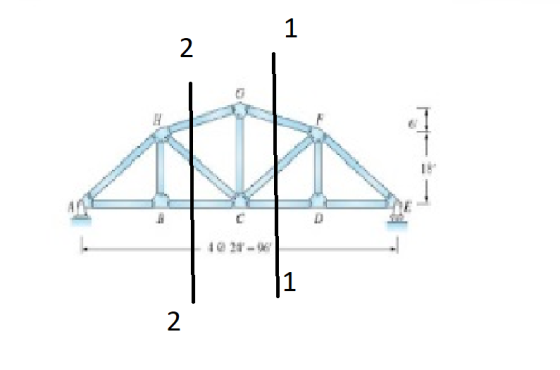
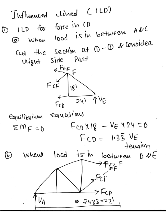
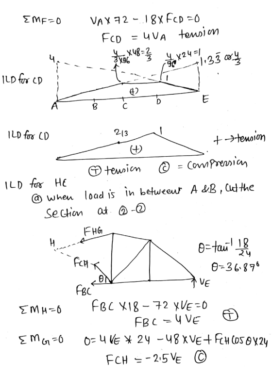
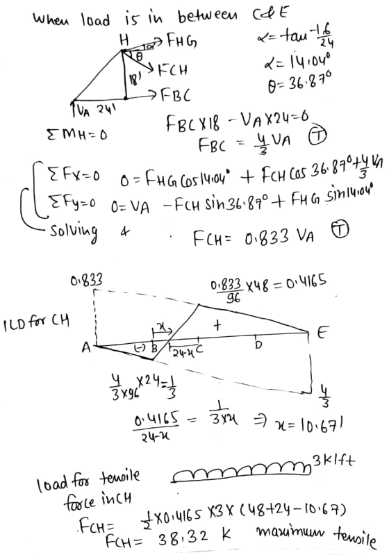
 Q2: Draw the influence lines for the members HC and CD of the truss shown in Fig. (2), and then determine the maximum tensile force that can be developed in member HC due to moving uniform distributed load of 3k/ft. 25% 18 с D 4@24-26 (2
Q2: Draw the influence lines for the members HC and CD of the truss shown in...
 Q2: Draw the influence lines for the members HC and CD
of the truss shown in Fig. (2), and then determine the maximum
tensile force that can be developed in member HC due to moving
uniform distributed load of 3k/ft.
I need it in 30min or 1 h
Н 18 B D с L 424-96 Fig. (2)
Q2: Draw the influence lines for the members HC and CD
of the truss shown in Fig. (2), and then determine the maximum
tensile force that can be developed in member HC due to moving
uniform distributed load of 3k/ft.
I need it in 30min or 1 h
Н 18 B D с L 424-96 Fig. (2)
Q2: Draw the influence lines for the members HC and CD of the truss shown in...
 Q2: Draw the influence lines for the members HC and CD of the truss shown in Fig. (2), and then determine the maximum tensile force that can be developed in member HC due to moving uniform distributed load of 3k/ft. 1.2 kft Pin 25 15ft 15k 2011 151 w 30 ft Fig. () Fig. (2) 10 2m 10 R S AGB B -1.5m +1.5 m 21 20 KN Ecom 40KN Fig. (3) Fig. (4) SO KN 200 N. Fig. (5)
2.) (a) Draw the influence lines for the bar forces in members HG and CD of...
 2.) (a) Draw the influence lines for the bar forces in members HG and CD of the truss shown below. The load moves along the bottom chord of the truss; (b) Compute the forces in members HG and CD if panel points B, C, and D are each loaded by a concentrated vertical load of 12 kips. (25 ponts) 6 18'
Q.3 For the non-parallel chord truss bridge shown in Fig. 3(a) (1) determine the influence lines...
 Q.3 For the non-parallel chord truss bridge shown in Fig. 3(a) (1) determine the influence lines for Fco, Fca and Fee: (2) The bridge is to be designed for the equivalent moving load detailed in Fig. 3(b). Compute the maximum tensile and compressive axial forces in member Cd. (Answer: Fcd max, T = 133.46 kN) L L P-115 kN JI ,-10 kN/m 4.5m 6@5m (Note that L2 may be varied or split up to achieve the desired effects, and that...
Problem #11 Draw the influence line for the force in member IH of the bridge truss....
 Problem #11 Draw the influence line for the force in member IH of the bridge truss. Determine the maximum force (tension or compression) that can be developed in this member due to a 72-k truck having the wheel loads shown. Assume the truck can travel in either direction along the center of the deck, so that half its load is transferred to each of the two side trusses. Also assume the members are pin connected at the gusset plates. 32...
pz explain. 6-58. Draw the influence line for the force in member CF, and then determine...
 pz explain.
6-58. Draw the influence line for the force in member CF, and then determine the maximum force (tension or compression) that can be developed in this member due to a uniform live load of 800 lb/ft which is transmitted to the truss along the bottom cord. AL 10 ft 10ft--.--10 ft 10 ft
pz explain.
6-58. Draw the influence line for the force in member CF, and then determine the maximum force (tension or compression) that can be developed in this member due to a uniform live load of 800 lb/ft which is transmitted to the truss along the bottom cord. AL 10 ft 10ft--.--10 ft 10 ft
The truss shown is used to support the floor deck. The uniform load on the deck...
 The truss shown is used to support the floor deck. The uniform load on the deck is 3k/ft. This load is transferred from the deck to the floor beams which rest on the top joints of the truss Determine the force in cach member of the truss, and state if the members are in tension or compression Assume all members are pin connected 16 I1 12 m 12 1 12 n
(a) Warren truss (b) Howe truss (c) Pratt truss (d) Baltimore truss (e) Parker truss Figure...
 (a) Warren truss (b) Howe truss (c) Pratt truss (d) Baltimore truss (e) Parker truss Figure 2: Truss Types (Nielson Text) The truss bridge has the following properties/characteristics: 1. Span length (bottom chord): 168 ft 2. 14 panels (12 ft length per panel) 3. All diagonals are 45 degrees 4. Simple truss (all members are pin-connected and loads are only applied at the joints) 5. Simply-supported (pin at one end, roller at the other) 6. 13 ft width between trusses...
Question 1 A truss has dimensions and subjected to loading as shown in Fig.1 1. Draw...
 Question 1 A truss has dimensions and subjected to loading as shown in Fig.1 1. Draw the influence line for the internal force of member GD Using the influence line to determine the internal axial force in member GD There is a uniform live load (q=3kN/m) applied on a part of the bottom chord. Determine the location of the live 2. 3. load which create the minimum axial load in member GD. 2m 2m 2m F D 2m G 10kN...
 Q2: Draw the influence lines for the members HC and CD of the truss shown in Fig. (2), and then determine the maximum tensile force that can be developed in member HC due to moving uniform distributed load of 3k/ft. 25% 18 с D 4@24-26 (2
 Q2: Draw the influence lines for the members HC and CD
of the truss shown in Fig. (2), and then determine the maximum
tensile force that can be developed in member HC due to moving
uniform distributed load of 3k/ft.
I need it in 30min or 1 h
Н 18 B D с L 424-96 Fig. (2)
Q2: Draw the influence lines for the members HC and CD
of the truss shown in Fig. (2), and then determine the maximum
tensile force that can be developed in member HC due to moving
uniform distributed load of 3k/ft.
I need it in 30min or 1 h
Н 18 B D с L 424-96 Fig. (2)
 Q2: Draw the influence lines for the members HC and CD of the truss shown in Fig. (2), and then determine the maximum tensile force that can be developed in member HC due to moving uniform distributed load of 3k/ft. 1.2 kft Pin 25 15ft 15k 2011 151 w 30 ft Fig. () Fig. (2) 10 2m 10 R S AGB B -1.5m +1.5 m 21 20 KN Ecom 40KN Fig. (3) Fig. (4) SO KN 200 N. Fig. (5)
 2.) (a) Draw the influence lines for the bar forces in members HG and CD of the truss shown below. The load moves along the bottom chord of the truss; (b) Compute the forces in members HG and CD if panel points B, C, and D are each loaded by a concentrated vertical load of 12 kips. (25 ponts) 6 18'
 Q.3 For the non-parallel chord truss bridge shown in Fig. 3(a) (1) determine the influence lines for Fco, Fca and Fee: (2) The bridge is to be designed for the equivalent moving load detailed in Fig. 3(b). Compute the maximum tensile and compressive axial forces in member Cd. (Answer: Fcd max, T = 133.46 kN) L L P-115 kN JI ,-10 kN/m 4.5m 6@5m (Note that L2 may be varied or split up to achieve the desired effects, and that...
 Problem #11 Draw the influence line for the force in member IH of the bridge truss. Determine the maximum force (tension or compression) that can be developed in this member due to a 72-k truck having the wheel loads shown. Assume the truck can travel in either direction along the center of the deck, so that half its load is transferred to each of the two side trusses. Also assume the members are pin connected at the gusset plates. 32...
 pz explain.
6-58. Draw the influence line for the force in member CF, and then determine the maximum force (tension or compression) that can be developed in this member due to a uniform live load of 800 lb/ft which is transmitted to the truss along the bottom cord. AL 10 ft 10ft--.--10 ft 10 ft
pz explain.
6-58. Draw the influence line for the force in member CF, and then determine the maximum force (tension or compression) that can be developed in this member due to a uniform live load of 800 lb/ft which is transmitted to the truss along the bottom cord. AL 10 ft 10ft--.--10 ft 10 ft
 The truss shown is used to support the floor deck. The uniform load on the deck is 3k/ft. This load is transferred from the deck to the floor beams which rest on the top joints of the truss Determine the force in cach member of the truss, and state if the members are in tension or compression Assume all members are pin connected 16 I1 12 m 12 1 12 n
 (a) Warren truss (b) Howe truss (c) Pratt truss (d) Baltimore truss (e) Parker truss Figure 2: Truss Types (Nielson Text) The truss bridge has the following properties/characteristics: 1. Span length (bottom chord): 168 ft 2. 14 panels (12 ft length per panel) 3. All diagonals are 45 degrees 4. Simple truss (all members are pin-connected and loads are only applied at the joints) 5. Simply-supported (pin at one end, roller at the other) 6. 13 ft width between trusses...
 Question 1 A truss has dimensions and subjected to loading as shown in Fig.1 1. Draw the influence line for the internal force of member GD Using the influence line to determine the internal axial force in member GD There is a uniform live load (q=3kN/m) applied on a part of the bottom chord. Determine the location of the live 2. 3. load which create the minimum axial load in member GD. 2m 2m 2m F D 2m G 10kN...
Most questions answered within 3 hours.
-
Let C = (2.25 m, 15 ∘ above the negative x-axis) and D = (30.6
m,...
asked 5 minutes ago -
of the following statements below is/are an example of a
normative statement?
I. The water shortage...
asked 7 minutes ago -
Carbon disulfide is prepared by heating sulfur and charcoal. The
chemical equation is
S2(g)+C(s)−⇀↽−CS2(g) Kc=9.40 at...
asked 11 minutes ago -
complete the problem and solution paragraph below, include 2-3
causes and 2-3 solutions for them.
remember...
asked 13 minutes ago -
I was looking for help with a computer science c programming
class. not c++
This program...
asked 37 minutes ago -
Albinism is an autosomal recessive condition characterized by
absence of melanin pigment from the skin, eye...
asked 27 minutes ago -
Suppose you're looking at a physics example online, and come
across this expression in the middle...
asked 35 minutes ago -
Compile a list (7 or more) of other commands useful for
navigating or manipulating the UNIX/Linux...
asked 44 minutes ago -
How many grams of PbBr2 will precipitate when excess CrBr3
solution is added to 61.0 mL...
asked 47 minutes ago -
If I was given the address of 134.15.0.0/16 from my ISP and I
wanted to use...
asked 51 minutes ago -
What is the pH of the solution that results of dissolving 1.74g
of sodium hydroxide in...
asked 55 minutes ago -
Given a standardized normal distribution (with μ = 0 and a σ =
1), what is...
asked 1 hour ago