


Homework Answers
Answer

QUESTION 14 in the circuit shown, E - 28.0 V, R1 -6.00 S2, R3 - 12.09,...
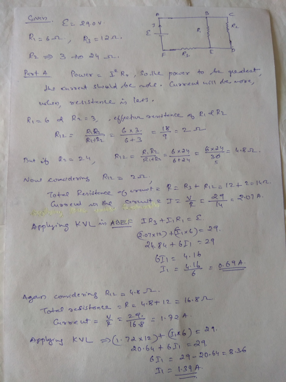
 QUESTION 14 in the circuit shown, E - 28.0 V, R1 -6.00 S2, R3 - 12.09, and R2 can vary between 3.00 and 29.09. For what value of R2 is the power dissipated by heating element R, the greatest? Calculate the magnitude of the greatest power.
Part 1 You have three resistors, R1 = 7,00 32, R2 = 8.00 12, and R3...
 Part 1 You have three resistors, R1 = 7,00 32, R2 = 8.00 12, and R3 = 9.00 32, connected as shown in (Figure 2). The terminals of a battery with emf 12.0 V and negligible internal resistance are connected to points a and b. Find the power output of the battery. Express your answer with the appropriate units. Part J Find the power input to Ri. Express your answer with the appropriate units. Part 6 Find the power input...
Problem 4.14 The circuit shown in figure(Figure 1)is a dc model of a residential power distribution...
 Problem 4.14 The circuit shown in figure(Figure 1)is a dc model of a residential power distribution circuit. Use the node- voltage method to find the branch currents ij - in if R1 = 2.022, R2 = 4.022, R3 = 2.012, R4 = 12.02, Rs = 24.0 2, R6 = 48.0 22 Part A Find the value of j. Express your answer with the appropriate units. IT HÅ ? i = Value Units Submit Request Answer Parte Find the value of...
A Review Constants In the circuit of the figure (Figure 1), take E = 12.0 V,...
 A Review Constants In the circuit of the figure (Figure 1), take E = 12.0 V, Ex = 6.00 V. Ez = 3.00 V, R1 = 1.10 12. R2 = 2.00 12 and R3 = 6.00 12 Part A Find the current in R, and give its direction Express your answer with the appropriate units. Enter positive value if the current flows from right to left and negative value if the current flows from left to right. LO1 HA ?...
Find Power at R1, R2, and R3 Consider the circuit shown in (Figure 1). The source...
 Find Power at R1, R2, and
R3
Consider the circuit shown in (Figure 1). The source voltage viis 45 V. Resistance R1, R2 and R3 are 5 12,115 1 and 2512, respectively. The source current I is 20 mA. Find PR Express your answer to three significant figures and include the appropriate units. Ao aj ? Value Units PR = Submit Request Answer Part E Figure < 1 of 1 Find PR Express your answer to three significant figures and...
Find Power at R1, R2, and
R3
Consider the circuit shown in (Figure 1). The source voltage viis 45 V. Resistance R1, R2 and R3 are 5 12,115 1 and 2512, respectively. The source current I is 20 mA. Find PR Express your answer to three significant figures and include the appropriate units. Ao aj ? Value Units PR = Submit Request Answer Part E Figure < 1 of 1 Find PR Express your answer to three significant figures and...
Four resistors and a battery are connected as shown in the figure. 10.02 6.00 52 w...
 Four resistors and a battery are connected as shown in the figure. 10.02 6.00 52 w 8.00 22 W w 3.002 30.0 V Part A Find the power delivered by the 30.0 V source. Express your answer with the appropriate units. | НА ? Value Units Part B Find the power dissipated by the 6.00-12 resistor. Express your answer with the appropriate units. НА ? Value Units Submit Request Answer Part Find the voltage across the 8.00- resistor. Express your...
Item 8 In the circuit shown in (Figure 1), E = 61.0 V, R4.00 1, R2...
 Item 8 In the circuit shown in (Figure 1), E = 61.0 V, R4.00 1, R2 = 6.00 2 and Ry = 3.00 n. For the 6.00 2 resistor, calculate the current through the resistor with S closed. Express your answer with the appropriate units. HA I = 4 Request Answer Submit Previous Answers X Incorrect; Try Again; One attempt remaining 1 of 1 Figure Part G b. R1 For the 3.00 2 resistor, calculate the current through the resistor...
Problem 4.7 Consider the circuit shown in (Figure 1). The source voltage v1 is 40 V....
 Problem 4.7 Consider the circuit shown in (Figure 1). The source voltage v1 is 40 V. Resistance R1, R2 and R3 are 5 ,120 and 15 , respectively. The source current I is 25 mA Part A Find the power developed by the current source I in the circuit. Express your answer to three significant figures and include the appropriate units. НА Value Units Рi 3 Request Answer Submit Part B Figure 1 of 1 Find the power developed by...
Item 8 In the circuit shown in (Figure 1). E = 66.0 V. R = 4,00...
 Item 8 In the circuit shown in (Figure 1). E = 66.0 V. R = 4,00 32 R2 = 6.00 N and R3 = 3.00 12 Figure 1 of 1 W Copyright © 2 We were unable to transcribe this imagePart D For the 4.00 12 resistor, calculate the current through the resistor with S closed. Express your answer with the appropriate units. HÅ ROO? 1 = | Value A Submit Request Answer Part E For the 6.00 12 resistor,...
Consider the circuit shown in (Figure 1). Suppose that V, = 415 0°V (rms). 4 Ω...
 Consider the circuit shown in (Figure 1). Suppose that V, = 415 0°V (rms). 4 Ω ν j3ΩΙ 120 Ω + j90 Ω Source- Line - Load Find the average power dissipated in the line in the figure. Express your answer to three significant figures and include the appropriate units. t НА ? ? P= Value Units Find the capacitive reactance that, when connected in parallel, with the load will make the load look purely resistive. Express your answer to...
 QUESTION 14 in the circuit shown, E - 28.0 V, R1 -6.00 S2, R3 - 12.09, and R2 can vary between 3.00 and 29.09. For what value of R2 is the power dissipated by heating element R, the greatest? Calculate the magnitude of the greatest power.
 Part 1 You have three resistors, R1 = 7,00 32, R2 = 8.00 12, and R3 = 9.00 32, connected as shown in (Figure 2). The terminals of a battery with emf 12.0 V and negligible internal resistance are connected to points a and b. Find the power output of the battery. Express your answer with the appropriate units. Part J Find the power input to Ri. Express your answer with the appropriate units. Part 6 Find the power input...
 Problem 4.14 The circuit shown in figure(Figure 1)is a dc model of a residential power distribution circuit. Use the node- voltage method to find the branch currents ij - in if R1 = 2.022, R2 = 4.022, R3 = 2.012, R4 = 12.02, Rs = 24.0 2, R6 = 48.0 22 Part A Find the value of j. Express your answer with the appropriate units. IT HÅ ? i = Value Units Submit Request Answer Parte Find the value of...
 A Review Constants In the circuit of the figure (Figure 1), take E = 12.0 V, Ex = 6.00 V. Ez = 3.00 V, R1 = 1.10 12. R2 = 2.00 12 and R3 = 6.00 12 Part A Find the current in R, and give its direction Express your answer with the appropriate units. Enter positive value if the current flows from right to left and negative value if the current flows from left to right. LO1 HA ?...
 Find Power at R1, R2, and
R3
Consider the circuit shown in (Figure 1). The source voltage viis 45 V. Resistance R1, R2 and R3 are 5 12,115 1 and 2512, respectively. The source current I is 20 mA. Find PR Express your answer to three significant figures and include the appropriate units. Ao aj ? Value Units PR = Submit Request Answer Part E Figure < 1 of 1 Find PR Express your answer to three significant figures and...
Find Power at R1, R2, and
R3
Consider the circuit shown in (Figure 1). The source voltage viis 45 V. Resistance R1, R2 and R3 are 5 12,115 1 and 2512, respectively. The source current I is 20 mA. Find PR Express your answer to three significant figures and include the appropriate units. Ao aj ? Value Units PR = Submit Request Answer Part E Figure < 1 of 1 Find PR Express your answer to three significant figures and...
 Four resistors and a battery are connected as shown in the figure. 10.02 6.00 52 w 8.00 22 W w 3.002 30.0 V Part A Find the power delivered by the 30.0 V source. Express your answer with the appropriate units. | НА ? Value Units Part B Find the power dissipated by the 6.00-12 resistor. Express your answer with the appropriate units. НА ? Value Units Submit Request Answer Part Find the voltage across the 8.00- resistor. Express your...
 Item 8 In the circuit shown in (Figure 1), E = 61.0 V, R4.00 1, R2 = 6.00 2 and Ry = 3.00 n. For the 6.00 2 resistor, calculate the current through the resistor with S closed. Express your answer with the appropriate units. HA I = 4 Request Answer Submit Previous Answers X Incorrect; Try Again; One attempt remaining 1 of 1 Figure Part G b. R1 For the 3.00 2 resistor, calculate the current through the resistor...
 Problem 4.7 Consider the circuit shown in (Figure 1). The source voltage v1 is 40 V. Resistance R1, R2 and R3 are 5 ,120 and 15 , respectively. The source current I is 25 mA Part A Find the power developed by the current source I in the circuit. Express your answer to three significant figures and include the appropriate units. НА Value Units Рi 3 Request Answer Submit Part B Figure 1 of 1 Find the power developed by...
 Item 8 In the circuit shown in (Figure 1). E = 66.0 V. R = 4,00 32 R2 = 6.00 N and R3 = 3.00 12 Figure 1 of 1 W Copyright © 2 We were unable to transcribe this imagePart D For the 4.00 12 resistor, calculate the current through the resistor with S closed. Express your answer with the appropriate units. HÅ ROO? 1 = | Value A Submit Request Answer Part E For the 6.00 12 resistor,...
 Consider the circuit shown in (Figure 1). Suppose that V, = 415 0°V (rms). 4 Ω ν j3ΩΙ 120 Ω + j90 Ω Source- Line - Load Find the average power dissipated in the line in the figure. Express your answer to three significant figures and include the appropriate units. t НА ? ? P= Value Units Find the capacitive reactance that, when connected in parallel, with the load will make the load look purely resistive. Express your answer to...
Most questions answered within 3 hours.
-
explain using physics theory either one
Why should you not put foil in the microwave? or...
asked 21 seconds ago -
A large distributor has 8 retail outlets. Currently each outlet
manages its ordering independently. Demand at...
asked 1 minute ago -
9 A website that facilitates transactions by bringing together
buyers and sellers from all over the...
asked 2 minutes ago -
Write a command line to view the long listing of all files,
including hidden files, with...
asked 35 minutes ago -
What kind of experiment would allow you to test that the
posterior cytoplasm can cause the...
asked 15 minutes ago -
Code in C++ please!
Write a function that takes an array of integers as an input...
asked 16 minutes ago -
Predict the reactions, if any, when the
following hydrogen compounds are added to water, and
explain...
asked 35 minutes ago -
What is the expression for the uncertainty in the total energy
Etot of equation?
Assume an...
asked 38 minutes ago -
A sledge loaded with bricks has a total mass of 18.5 kg and is
pulled at...
asked 30 minutes ago -
In response to the increasing weight of airline passengers, the
Federal Aviation Administration told airlines to...
asked 38 minutes ago -
Events A and B are independent. Suppose event A occurs with
probability 0.63 and event B...
asked 48 minutes ago -
Rubies are essentially alumina Al2O3 with a contaminant of
chromium in the form of Cr2O3. A...
asked 56 minutes ago