
Homework Answers


![Demben AD ; 2=552, 0 = 6.4.5 Uy 0.707 -0.707 -0.707 0,707 0.707] 5 Uu - - 5.6418 N Hence, NABE 8.52 N NACE o NBD = -Q66.1 N N](http://img.homeworklib.com/questions/c241a440-113f-11eb-9228-c16c585f262f.png?x-oss-process=image/resize,w_560)
Add Answer to:
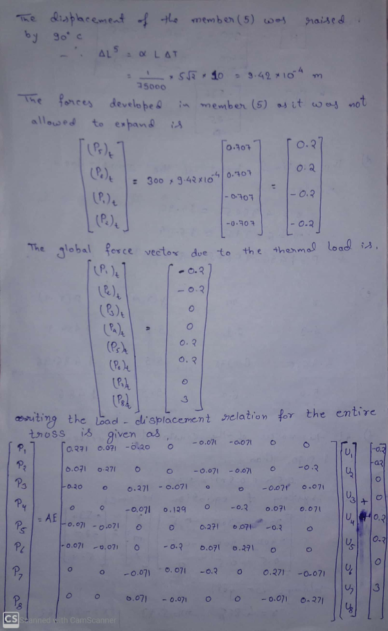
For the truss shown in the following figure, the temperature of member BC is raised by...
For the truss shown in the following figure, the temperature of member BC is raised by...
 For
the truss shown in the following figure, the temperature of member
BC is raised by 50 ∘C, and member BD is raised by 80 ∘C. EA= 300000
N for all members and α= 1/75000 1/∘C. Use the stiffness method to
do the following:
Week 8, Question 1: For the truss shown in the following figure, the temperature of member BC is raised by 50 °C, and member BD is raised by 80 °C. EA= 300000 N for all members...
For
the truss shown in the following figure, the temperature of member
BC is raised by 50 ∘C, and member BD is raised by 80 ∘C. EA= 300000
N for all members and α= 1/75000 1/∘C. Use the stiffness method to
do the following:
Week 8, Question 1: For the truss shown in the following figure, the temperature of member BC is raised by 50 °C, and member BD is raised by 80 °C. EA= 300000 N for all members...
the required data is there , just need to caslculate it Week 8, Question 1: For...
 the
required data is there , just need to caslculate it
Week 8, Question 1: For the truss shown in the following figure, the temperature of member BC is raised by 60 °C, and member BD is raised by 40 °C. EA= 300000 N for all members and a= 1/75000 18 C. Use the stiffness method to do the following: B 5 m с D Part 1. Calculate the displacements at the joints: a) Ax = mm b) Ay =...
the
required data is there , just need to caslculate it
Week 8, Question 1: For the truss shown in the following figure, the temperature of member BC is raised by 60 °C, and member BD is raised by 40 °C. EA= 300000 N for all members and a= 1/75000 18 C. Use the stiffness method to do the following: B 5 m с D Part 1. Calculate the displacements at the joints: a) Ax = mm b) Ay =...
Week 8, Question 2: Member AC of the following truss is subjected to a temperature change...
 Week 8, Question 2: Member AC of the following truss is subjected to a temperature change of +50 °C. Calculate the displacements of node A and the forces in each member using the stiffness method. Take: a= 2x 10⁻⁵; EA= 2x 10⁴ kN; the cross section area of AC as A; the cross section area of AD as AV2; the cross section area of AB as 2.0A. B 1.732 m 1 m D Part 1. The displacements at joint A:...
Week 8, Question 2: Member AC of the following truss is subjected to a temperature change...
 Week 8, Question 2: Member AC of the following truss is subjected to a temperature change of +50 °C. Calculate the displacements of node A and the forces in each member using the stiffness method. Take: a= 2x 10⁻⁵; EA= 2x 10⁴ kN; the cross section area of AC as A; the cross section area of AD as AV2; the cross section area of AB as 1A. B 1.732 m A 1 m D 1 m Part 1. The displacements...
Week 8, Question 2: Member AC of the following truss is subjected to a temperature change...
 Week 8, Question 2: Member AC of the following truss is subjected to a temperature change of +80 °C. Calculate the displacements of node A and the forces in each member using the stiffness method. Take: a= 2x 10⁻⁵; EA= 2x 10⁴ kN; the cross section area of AC as A; the cross section area of AD as A 2; the cross section area of AB as 1A. 1.732 m I'm kim Part 1. The displacements at joint A: a)...
Estimate the redundant force in the truss member BC as shown in the following FIGURE. The...
 Estimate the redundant force in the truss member BC as shown in the following FIGURE. The truss is subjected to a vertical load P as 50 kN. Members AB, AC, CD, and BD are 5 m long. The cross-sectional area of all members is constant. The support at A is the pin support and the support at B is the roller support. P = 50 kN Ан, B Av Ву
Truss ABCD is simply supported at joints A and C. Force F = 100 N and...
 Truss ABCD is simply supported at joints A and C. Force F = 100 N and acts downward at joint D. Length AB = BC = 4m and length BD = 3m. Determine the force (N) acting in member BD and its direction. (use +### for tension and -### for compression). D B A С F
LO2, 12 Marks)- For the truss assembly shown, the loading and dimensions are as tab whether...
 LO2, 12 Marks)- For the truss assembly shown, the loading and dimensions are as tab whether each member is in tension or compression. Param Value Units 800 N 800 N 3.75 m 3.75 m aI Part A- The support reactions at A: Ay- Part B-The support reactions at F: Fx Part C-The force in BD is Part D-The force in DE is Part E- What joint should you consider for the calculations in Parts C, D? 수:N 수 N. 수N.
two-member truss is subjected to a load P 8000 N. Me mber 1-2 is 400 mm...
 two-member truss is subjected to a load P 8000 N. Me mber 1-2 is 400 mm long. 4.12. A ember 1-3 was manufactured to be 505 mm long instead of 500 mm. However, it was forced into place. Determine stresses in the members assuming that member 1-3 was manufactured to its correct (a) the length of 500 mm load P, of course). pression in the text.) Take cross-sectional areas 750 mm2, E 200 GPa (b) thestresses in the members as...
Po 13.6 kN Value Units Figure Part kN Part A Determine the force in member BC of the truss and ...
 Po 13.6 kN Value Units Figure Part kN Part A Determine the force in member BC of the truss and state if this member is in tension or compression. Express your answer to three significant figures and include the appropriate units. Enter negative value in the case of Consider the truss showm in (Figure 1). Set P1-6 kN, compression and positive value in the case of tension Figure 1 of 1 Poc 15.6 kN Submit X Incorrect; Try Again; 3...
 For
the truss shown in the following figure, the temperature of member
BC is raised by 50 ∘C, and member BD is raised by 80 ∘C. EA= 300000
N for all members and α= 1/75000 1/∘C. Use the stiffness method to
do the following:
Week 8, Question 1: For the truss shown in the following figure, the temperature of member BC is raised by 50 °C, and member BD is raised by 80 °C. EA= 300000 N for all members...
For
the truss shown in the following figure, the temperature of member
BC is raised by 50 ∘C, and member BD is raised by 80 ∘C. EA= 300000
N for all members and α= 1/75000 1/∘C. Use the stiffness method to
do the following:
Week 8, Question 1: For the truss shown in the following figure, the temperature of member BC is raised by 50 °C, and member BD is raised by 80 °C. EA= 300000 N for all members...
 the
required data is there , just need to caslculate it
Week 8, Question 1: For the truss shown in the following figure, the temperature of member BC is raised by 60 °C, and member BD is raised by 40 °C. EA= 300000 N for all members and a= 1/75000 18 C. Use the stiffness method to do the following: B 5 m с D Part 1. Calculate the displacements at the joints: a) Ax = mm b) Ay =...
the
required data is there , just need to caslculate it
Week 8, Question 1: For the truss shown in the following figure, the temperature of member BC is raised by 60 °C, and member BD is raised by 40 °C. EA= 300000 N for all members and a= 1/75000 18 C. Use the stiffness method to do the following: B 5 m с D Part 1. Calculate the displacements at the joints: a) Ax = mm b) Ay =...
 Week 8, Question 2: Member AC of the following truss is subjected to a temperature change of +50 °C. Calculate the displacements of node A and the forces in each member using the stiffness method. Take: a= 2x 10⁻⁵; EA= 2x 10⁴ kN; the cross section area of AC as A; the cross section area of AD as AV2; the cross section area of AB as 2.0A. B 1.732 m 1 m D Part 1. The displacements at joint A:...
 Week 8, Question 2: Member AC of the following truss is subjected to a temperature change of +50 °C. Calculate the displacements of node A and the forces in each member using the stiffness method. Take: a= 2x 10⁻⁵; EA= 2x 10⁴ kN; the cross section area of AC as A; the cross section area of AD as AV2; the cross section area of AB as 1A. B 1.732 m A 1 m D 1 m Part 1. The displacements...
 Week 8, Question 2: Member AC of the following truss is subjected to a temperature change of +80 °C. Calculate the displacements of node A and the forces in each member using the stiffness method. Take: a= 2x 10⁻⁵; EA= 2x 10⁴ kN; the cross section area of AC as A; the cross section area of AD as A 2; the cross section area of AB as 1A. 1.732 m I'm kim Part 1. The displacements at joint A: a)...
 Estimate the redundant force in the truss member BC as shown in the following FIGURE. The truss is subjected to a vertical load P as 50 kN. Members AB, AC, CD, and BD are 5 m long. The cross-sectional area of all members is constant. The support at A is the pin support and the support at B is the roller support. P = 50 kN Ан, B Av Ву
 Truss ABCD is simply supported at joints A and C. Force F = 100 N and acts downward at joint D. Length AB = BC = 4m and length BD = 3m. Determine the force (N) acting in member BD and its direction. (use +### for tension and -### for compression). D B A С F
 LO2, 12 Marks)- For the truss assembly shown, the loading and dimensions are as tab whether each member is in tension or compression. Param Value Units 800 N 800 N 3.75 m 3.75 m aI Part A- The support reactions at A: Ay- Part B-The support reactions at F: Fx Part C-The force in BD is Part D-The force in DE is Part E- What joint should you consider for the calculations in Parts C, D? 수:N 수 N. 수N.
 two-member truss is subjected to a load P 8000 N. Me mber 1-2 is 400 mm long. 4.12. A ember 1-3 was manufactured to be 505 mm long instead of 500 mm. However, it was forced into place. Determine stresses in the members assuming that member 1-3 was manufactured to its correct (a) the length of 500 mm load P, of course). pression in the text.) Take cross-sectional areas 750 mm2, E 200 GPa (b) thestresses in the members as...
 Po 13.6 kN Value Units Figure Part kN Part A Determine the force in member BC of the truss and state if this member is in tension or compression. Express your answer to three significant figures and include the appropriate units. Enter negative value in the case of Consider the truss showm in (Figure 1). Set P1-6 kN, compression and positive value in the case of tension Figure 1 of 1 Poc 15.6 kN Submit X Incorrect; Try Again; 3...
Most questions answered within 3 hours.
-
The pH of a sample of water from a river is 5.0. A
sample of effluent from...
asked 10 minutes ago -
At the beginning of the period, the Fabricating Department
budgeted direct labor of $136,500 and equipment...
asked 38 minutes ago -
Please answer all
____ 28. Rent control is usually
justified on the grounds that it protects...
asked 37 minutes ago -
PARTS A-D HAVE BEEN ANSWERED. WAS TOLD TO REPOST. ONLY ANSWER
PARTS E and F.
A...
asked 55 minutes ago -
2) You are given the task of finding a representation for a
circle in a drawing...
asked 2 hours ago -
STUDY QUESTION: Does use of diet drug fen-phen
(fenfluramine-phentermine) cause valvular heart disease?
HINT: Valvular heart...
asked 1 hour ago -
1. An object weighing 40 N rests on a surface. The coefficient
of friction is 0.35....
asked 3 hours ago -
Investor company owns 35% of investee company voting stock and
accounts for the investment under the...
asked 4 hours ago -
The number of major faults on a randomly chosen 1 km stretch of
highway has a...
asked 4 hours ago -
Consider the competitive environment of Starbuck's, Progressive
Insurance, a manufacturing firm with low turnover, or a...
asked 5 hours ago -
3. Gains from trade
Consider two neighbouring island countries called Euphoria and
Contente. They each have...
asked 7 hours ago -
A business executive has the option to invest money in two
plans: Plan A guarantees that...
asked 9 hours ago