Please solve both parts a and b step-by-step using the block reduction method ONLY.
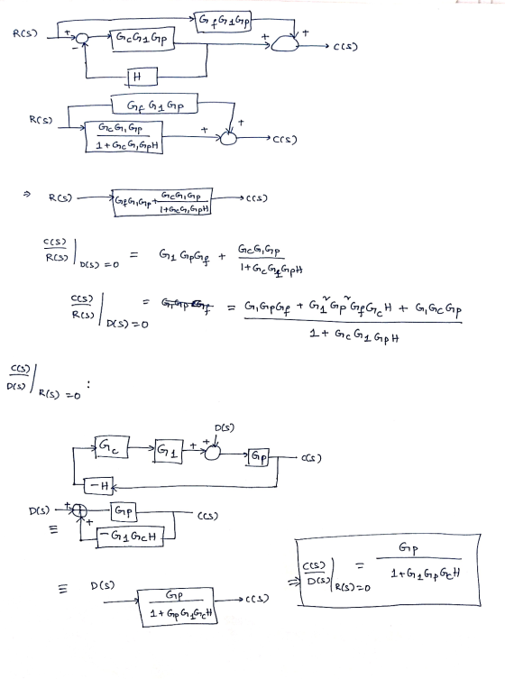
![Q4 a) (1 mark) The figure below shows a block diagram of a control system, obtain the transfer function [Y(s)/R(s)]N=0 N(S) R](http://img.homeworklib.com/questions/61ed7f50-03a3-11eb-b2b5-e97505104861.png?x-oss-process=image/resize,w_560)
Homework Answers

![111 R(S) 1+GE(S) HCS) Gpls) 1+ Gpls) HIS) →y(s) > R(s) Gp(s)[1 + GC687 H (s)] 1+ Gpls) HIS) →y(s) * YCS) Gpso 1 + GeCs) H(s)]](http://img.homeworklib.com/questions/87aff340-03a3-11eb-8d25-0d8e691b3814.png?x-oss-process=image/resize,w_560)
Add Answer to:
Please solve both parts a and b step-by-step using the block
reduction method ONLY.
Q4 a)...
R E UA Given the block diagram as shown, R and D are inputs and G,...
 R E UA Given the block diagram as shown, R and D are inputs and G, G, and H, are transfer functions. a) Using only the block diagram reduction G G method", find the transfer function C/R in terms of G, G, and H. H, b) Using only the block diagram reduction method*, find the transfer function E/D in terms of G, G, and Hz. c) Using either the block diagram reduction method* or the equation method, find the transfer...
03. (a) Consider the block diagram shown in Figure 3.1, and assume G(s)= 3. G,(s) and...
 03. (a) Consider the block diagram shown in Figure 3.1, and assume G(s)= 3. G,(s) and G,(s) 5+2 Y(s) R(S) G,() Gy(s) G;(s) Figure 3.1 3 (0) Y(s) Derive the system transfer function H(s)= of the system. Plot the R(s) poles and zeros of H(s) in the complex s-plane. State whether the system is stable or not stable, and why. [10 marks) (11) Obtain the impulse response of the system, that is ylt) for r(t)= 8(t). Evaluate the final value...
Problem 1 Block Diagram Reduction Use the block diagram reduction method to compute the transfer function...
 Problem 1 Block Diagram Reduction Use the block diagram reduction method to compute the transfer function ()/R(8). Show work! Ab R(s) 0 FIGURE 7.27. Block diagram reduction.
4. E G > G. b) Given the block diagram as shown, R and D are...
 4. E G > G. b) Given the block diagram as shown, R and D are inputs and G, G, and H, are transfer functions. a) Using only the block diagram reduction R с method*, find the transfer function C/R in terms of G, G, and Hz. H, Using only the block diagram reduction method*, find the transfer function E/D in terms of G, G,, and Hy c) Using either the block diagram reduction method* or the equation method, find...
Please code on MATLAB and explain D) only. Thank you The block diagram of a linear...
 Please code on MATLAB and explain D) only. Thank you
The block diagram of a linear control system is shown in the Fig., where r(t) is the reference input and n(t) is the disturbance. (a) Find the steady-state value of e(t) when n(t) = 0 and r(t) tuz(t). Find the conditions on the values of a and K so that the solution is valid. N(s) R(S) E(S) S + a K(s + 3) Y(s) S (5² - 1) Controller Process...
Please code on MATLAB and explain D) only. Thank you
The block diagram of a linear control system is shown in the Fig., where r(t) is the reference input and n(t) is the disturbance. (a) Find the steady-state value of e(t) when n(t) = 0 and r(t) tuz(t). Find the conditions on the values of a and K so that the solution is valid. N(s) R(S) E(S) S + a K(s + 3) Y(s) S (5² - 1) Controller Process...
R+ E vo UA G G b) Given the block diagram as shown, R and D...
 R+ E vo UA G G b) Given the block diagram as shown, R and D are inputs and G, G, and H, are transfer functions. D a) Using only the block diagram reduction method*, find the transfer function C/R in terms of G, G2, and H2 HA Using only the block diagram reduction method*, find the transfer function E/D in terms of G, G, and Hz. c) Using either the block diagram reduction method* or the equation method, find...
4. Given the block diagram as shown, and D are inputs and G, G2, and H,...
 4. Given the block diagram as shown, and D are inputs and G, G2, and H, are transfer functions. a) Using only the block diagram reduction R+ G method*, find the transfer function C/R in terms of G, G, and Hz. H b) Using only the block diagram reduction method*, find the transfer function E/D in terms of G, G2, and Hz. c) Using either the block diagram reduction method* or the equation method, find the transfer function E/R in...
PROBLEMS B-2-1. Simplify the block diagram shown in Figure 2-29 and obtain the closed-loop transfer function...
 PROBLEMS B-2-1. Simplify the block diagram shown in Figure 2-29 and obtain the closed-loop transfer function C(s)/RS). B-2-2. Simplify the block diagram shown in Figure 2-30 and obtain the closed-loop transfer function C(s)/R(s). B-2-3. Simplify the block diagram shown in Figure 2-31 and obtain the closed-loop transfer function C(s)/R(S). G1 R(S) CS) Figure 2-29 Block diagram of a system. Figure 2-30 Block diagram of a system. Figure 2-31 Block diagram of a system.
Q4. The feedback system shown below has a plant, a controller, and sensor transfer functions as...
 Q4. The feedback system shown below has a plant, a controller, and sensor transfer functions as G(s), Gc(s) and H(s), respectively. Find the output Y(s) and the input U(s) as a function of the inputs and transfer functions. (2 Points) D(s) R(s) + U(s) Gc (s) O G(s) - Y(s) H(S)
4 (a) Based on the block diagram for a control system (Figure Q4(a) below) determine the...
 4 (a) Based on the block diagram for a control system (Figure Q4(a) below) determine the transfer function between the error and the set point, E(s)/R(s) (8 marks) R(s)+ c(p) m(s) Figure Q4(a) Figure Q4(b) below shows two different control strategies for a continuous stirred tank reactor (CSTR). The reaction A → B is exothermic and the heat generated is removed by the coolant flowing through the jacket. It is assumed the flowrate of the reactor feed is fixed. Two...
 R E UA Given the block diagram as shown, R and D are inputs and G, G, and H, are transfer functions. a) Using only the block diagram reduction G G method", find the transfer function C/R in terms of G, G, and H. H, b) Using only the block diagram reduction method*, find the transfer function E/D in terms of G, G, and Hz. c) Using either the block diagram reduction method* or the equation method, find the transfer...
 03. (a) Consider the block diagram shown in Figure 3.1, and assume G(s)= 3. G,(s) and G,(s) 5+2 Y(s) R(S) G,() Gy(s) G;(s) Figure 3.1 3 (0) Y(s) Derive the system transfer function H(s)= of the system. Plot the R(s) poles and zeros of H(s) in the complex s-plane. State whether the system is stable or not stable, and why. [10 marks) (11) Obtain the impulse response of the system, that is ylt) for r(t)= 8(t). Evaluate the final value...
 Problem 1 Block Diagram Reduction Use the block diagram reduction method to compute the transfer function ()/R(8). Show work! Ab R(s) 0 FIGURE 7.27. Block diagram reduction.
 4. E G > G. b) Given the block diagram as shown, R and D are inputs and G, G, and H, are transfer functions. a) Using only the block diagram reduction R с method*, find the transfer function C/R in terms of G, G, and Hz. H, Using only the block diagram reduction method*, find the transfer function E/D in terms of G, G,, and Hy c) Using either the block diagram reduction method* or the equation method, find...
 Please code on MATLAB and explain D) only. Thank you
The block diagram of a linear control system is shown in the Fig., where r(t) is the reference input and n(t) is the disturbance. (a) Find the steady-state value of e(t) when n(t) = 0 and r(t) tuz(t). Find the conditions on the values of a and K so that the solution is valid. N(s) R(S) E(S) S + a K(s + 3) Y(s) S (5² - 1) Controller Process...
Please code on MATLAB and explain D) only. Thank you
The block diagram of a linear control system is shown in the Fig., where r(t) is the reference input and n(t) is the disturbance. (a) Find the steady-state value of e(t) when n(t) = 0 and r(t) tuz(t). Find the conditions on the values of a and K so that the solution is valid. N(s) R(S) E(S) S + a K(s + 3) Y(s) S (5² - 1) Controller Process...
 R+ E vo UA G G b) Given the block diagram as shown, R and D are inputs and G, G, and H, are transfer functions. D a) Using only the block diagram reduction method*, find the transfer function C/R in terms of G, G2, and H2 HA Using only the block diagram reduction method*, find the transfer function E/D in terms of G, G, and Hz. c) Using either the block diagram reduction method* or the equation method, find...
 4. Given the block diagram as shown, and D are inputs and G, G2, and H, are transfer functions. a) Using only the block diagram reduction R+ G method*, find the transfer function C/R in terms of G, G, and Hz. H b) Using only the block diagram reduction method*, find the transfer function E/D in terms of G, G2, and Hz. c) Using either the block diagram reduction method* or the equation method, find the transfer function E/R in...
 PROBLEMS B-2-1. Simplify the block diagram shown in Figure 2-29 and obtain the closed-loop transfer function C(s)/RS). B-2-2. Simplify the block diagram shown in Figure 2-30 and obtain the closed-loop transfer function C(s)/R(s). B-2-3. Simplify the block diagram shown in Figure 2-31 and obtain the closed-loop transfer function C(s)/R(S). G1 R(S) CS) Figure 2-29 Block diagram of a system. Figure 2-30 Block diagram of a system. Figure 2-31 Block diagram of a system.
 Q4. The feedback system shown below has a plant, a controller, and sensor transfer functions as G(s), Gc(s) and H(s), respectively. Find the output Y(s) and the input U(s) as a function of the inputs and transfer functions. (2 Points) D(s) R(s) + U(s) Gc (s) O G(s) - Y(s) H(S)
 4 (a) Based on the block diagram for a control system (Figure Q4(a) below) determine the transfer function between the error and the set point, E(s)/R(s) (8 marks) R(s)+ c(p) m(s) Figure Q4(a) Figure Q4(b) below shows two different control strategies for a continuous stirred tank reactor (CSTR). The reaction A → B is exothermic and the heat generated is removed by the coolant flowing through the jacket. It is assumed the flowrate of the reactor feed is fixed. Two...
Most questions answered within 3 hours.
-
Calculate the number density of argon gas at a temperature of
24C and a pressure of...
asked 2 hours ago -
Alternative
Classification
How to Estimate
Probabilities from Data? ( For continuous Attributes)
And How to generate...
asked 2 hours ago -
An explosion breaks a 20.0-kg object into three parts. The
object is initially moving at a...
asked 3 hours ago -
Calculate the approximate number of residues of Rubisco, which
is involved in carbon fixation in plants,...
asked 4 hours ago -
Other decisions about scientific claims can have a much broader
impact.ENERGYarrow-10x10.png, environment, health, security - all...
asked 5 hours ago -
I need to write a research paper and work cited about this
topic: The United States...
asked 6 hours ago -
Hello! I was wondering if I could have some help?
If the vapor pressure of carvone...
asked 6 hours ago -
An economist wants to estimate the mean per capita income (in
thousands of dollars) for a...
asked 6 hours ago -
What would be the input/output characteristic of a circuit
obtained by putting two of your 2's-complementers...
asked 6 hours ago -
In Drosophila, the transition from the syncytial blastoderm
stage to the cellular blastoderm stage is a...
asked 7 hours ago -
Project management question:
Name 3 different types of resources (hint: humans are one
type)
asked 7 hours ago -
Consider the following reaction: C 2H 2( g) + 2H 2( g) C 2H 6(
g)...
asked 7 hours ago