
Homework Answers
part a


Part b
Kirchoff rule


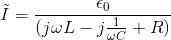
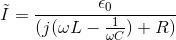
Part c


Part d

So


and

Part e

maximum I2 ocuurs at


Add Answer to:
Z, L mimi I -Ť → Eocoswt Figure 2: A series LCR circuit. 1. A series...
2. LRC series circuit. [10 pts.] Consider an LRC series circuit driven by an ac voltage source Vi...
 2. LRC series circuit. [10 pts.] Consider an LRC series circuit driven by an ac voltage source Vin Vo cos(wt). (a) Derive an expression for the real ac current in the circuit in terms of L, R, C, and a. (b) Determine the resonant frequency f, and angular frequency w, by direct differentiation of the current amplitude from part (a). Compare your result to LC (c) Determine the Q factor of this circuit in terms of L, R, and C....
Q13. For a series R-L circuit fed by a voltage V-Vmarcoso, give expressions for (a) the...
 Q13. For a series R-L circuit fed by a voltage V-Vmarcoso, give expressions for (a) the complex power; (b) the reactive power; (c) average power 014. For a parallel R-C circuit fed by a voltage V-Vmacoscor, give expressions for (a) the complex power; (b) the reactive power; (c) average power.
Given for a series LRC circuit that I=V/Z and that Z=[R2+(omega L-1/(omega C))2]1/2 explain the interesting...
Given for a series LRC circuit that I=V/Z and that Z=[R2+(omega L-1/(omega C))2]1/2 explain the interesting result about the current and power to R. These result from special values of R, L, and C
In a series L-R-C circuit, the components have the following values: L = 20.0 mH, C...
 In a series L-R-C circuit, the components have the following values: L = 20.0 mH, C = 140 nF, and R = 350 Ohm. The generator has an rms voltage 120 V and a frequency of 1.25 kHz. Part A Determine the average power supplied by the generator. P = W Submit My Answers Give Up Part B Determine the average power dissipated in the resistor. PR = W Submit My Answers Give Up
Pre-Laboratory Task 4: Derive an expression for the magnitude of the transfer function, H(Go)Vout(jo)/Wn(j, and the phase of the transfer function LH (ja) for the LCR circuit in Figure 4. Plot H(ja)l...
 Pre-Laboratory Task 4: Derive an expression for the magnitude of the transfer function, H(Go)Vout(jo)/Wn(j, and the phase of the transfer function LH (ja) for the LCR circuit in Figure 4. Plot H(ja)l and H(jo) vs. frequency (o) in the form of a Bode plot indicating the damping frequency and the value of |H(jo)| at the damping frequency. Also determine the 3dB frequency and the roll off rate for Ir(ja)1 when ω > ω3dB. Vounlius R 470Ω C 100 nF Figure...
Exercise 31.20 In a series L-R-C circuit, the components have the following values: L =20.0 mH....
 Exercise 31.20 In a series L-R-C circuit, the components have the following values: L =20.0 mH. C =140 nF and R= 350 2. The generator has an rms voltage of 120 V and a frequency of 1.25 kHz. Part A Determine the average power supplied by the generator ANSWER: P- w Part 8 Determine the average power dissipated in the resistor. ANSWER: PR- w
and R - 50.00 is in seconds, is applied to a series RLC circuit with L...
 and R - 50.00 is in seconds, is applied to a series RLC circuit with L = 170 mH, C = 99.0 A sinusoidal voltage Av 43.0 sin 100t, where av is in volts and (a) What is the impedance of the circuit? (b) What is the maximum current? lmay sin (out ). (c) Determine the numerical value for w in the equation i Trad/s in the equation / Imax sin ( - ). (d) Determine the numerical value for...
3. Natural response, for ? > 0 of a series R-L-C circuit has R = 1...
3. Natural response, for ? > 0 of a series R-L-C circuit has R = 1 Ω , L = 1 H and C = 1 F. The initial capacitor voltage is 4 V, and initial inductor current is zero. The series current is i. (i) Draw the time domain circuit. (ii) Draw the Laplace transform domain circuit. (iii) From (ii), determine Io =Io (s) (iv) From (iii), determine ?? = ??(?) for t > 0
Review | Constants A series L-R-C circuit is driven with AC voltage of amplitude Vin and...
 Review | Constants A series L-R-C circuit is driven with AC voltage of amplitude Vin and frequency w. Define Vout to be the amplitude of the voltage across the capacitor. The resistance of the resistor is R, the capacitance of the capacitor is C, and the inductance of the inductor is L. (Figure 1) Part A What is the ratio Viin Figure Express your answer in terms of either R, w, L, and C or R, XL = wl, and...
Question 4 In Figure Q4, a resistance, R is connected in series with an iron-cored choke coil (r in series with L). The circuit draws a current of 5 A at 240 V, 60 Hz. The voltages across the res...
 Question 4 In Figure Q4, a resistance, R is connected in series with an iron-cored choke coil (r in series with L). The circuit draws a current of 5 A at 240 V, 60 Hz. The voltages across the resistance and the coil are 100 V and 200 V respectively. Analyze the circuit to determine the following (a) the resistance, reactance and impedance of the coil, (b) the power absorbed by the coil, and (c) the power factor (pf) of...
 2. LRC series circuit. [10 pts.] Consider an LRC series circuit driven by an ac voltage source Vin Vo cos(wt). (a) Derive an expression for the real ac current in the circuit in terms of L, R, C, and a. (b) Determine the resonant frequency f, and angular frequency w, by direct differentiation of the current amplitude from part (a). Compare your result to LC (c) Determine the Q factor of this circuit in terms of L, R, and C....
 Q13. For a series R-L circuit fed by a voltage V-Vmarcoso, give expressions for (a) the complex power; (b) the reactive power; (c) average power 014. For a parallel R-C circuit fed by a voltage V-Vmacoscor, give expressions for (a) the complex power; (b) the reactive power; (c) average power.
 In a series L-R-C circuit, the components have the following values: L = 20.0 mH, C = 140 nF, and R = 350 Ohm. The generator has an rms voltage 120 V and a frequency of 1.25 kHz. Part A Determine the average power supplied by the generator. P = W Submit My Answers Give Up Part B Determine the average power dissipated in the resistor. PR = W Submit My Answers Give Up
 Pre-Laboratory Task 4: Derive an expression for the magnitude of the transfer function, H(Go)Vout(jo)/Wn(j, and the phase of the transfer function LH (ja) for the LCR circuit in Figure 4. Plot H(ja)l and H(jo) vs. frequency (o) in the form of a Bode plot indicating the damping frequency and the value of |H(jo)| at the damping frequency. Also determine the 3dB frequency and the roll off rate for Ir(ja)1 when ω > ω3dB. Vounlius R 470Ω C 100 nF Figure...
 Exercise 31.20 In a series L-R-C circuit, the components have the following values: L =20.0 mH. C =140 nF and R= 350 2. The generator has an rms voltage of 120 V and a frequency of 1.25 kHz. Part A Determine the average power supplied by the generator ANSWER: P- w Part 8 Determine the average power dissipated in the resistor. ANSWER: PR- w
 and R - 50.00 is in seconds, is applied to a series RLC circuit with L = 170 mH, C = 99.0 A sinusoidal voltage Av 43.0 sin 100t, where av is in volts and (a) What is the impedance of the circuit? (b) What is the maximum current? lmay sin (out ). (c) Determine the numerical value for w in the equation i Trad/s in the equation / Imax sin ( - ). (d) Determine the numerical value for...
 Review | Constants A series L-R-C circuit is driven with AC voltage of amplitude Vin and frequency w. Define Vout to be the amplitude of the voltage across the capacitor. The resistance of the resistor is R, the capacitance of the capacitor is C, and the inductance of the inductor is L. (Figure 1) Part A What is the ratio Viin Figure Express your answer in terms of either R, w, L, and C or R, XL = wl, and...
 Question 4 In Figure Q4, a resistance, R is connected in series with an iron-cored choke coil (r in series with L). The circuit draws a current of 5 A at 240 V, 60 Hz. The voltages across the resistance and the coil are 100 V and 200 V respectively. Analyze the circuit to determine the following (a) the resistance, reactance and impedance of the coil, (b) the power absorbed by the coil, and (c) the power factor (pf) of...
Most questions answered within 3 hours.
-
Give your answer in SI units and to three significant
figures.
A 2.3 m radius cylinder...
asked 1 minute ago -
Supply the missing quantities. (Assume P1 =
0.4, P2 = 0.6, P3 =
0.4.)
P(A ∩...
asked 6 minutes ago -
The chapter discusses four types of change that organizations
typically encounter—technological, structural, task, and people
change....
asked 5 minutes ago -
A sample of 12 grams of a substance that does not dissociate is
dissolved in 80...
asked 8 minutes ago -
What is the pH of a solution made by mixing 0.438 moles of HBr
and 0.304...
asked 8 minutes ago -
If it takes 100m to stop a car initially moving at 100 m/s
what distance is...
asked 21 minutes ago -
Two resistors have resistances R1 and R2. When the resistors are
connected in series to a...
asked 22 minutes ago -
Why do scientists infer that there were living organisms as far
back as 3.8 billion years...
asked 25 minutes ago -
if a palladium nanoparticle has a density of 12.0gxcm^3, what is
the mass of a nanoparticle...
asked 26 minutes ago -
If you are worried about performing 2 statistical tests on the
same data and that the...
asked 33 minutes ago -
Use Microsoft Excel to determine the rate of return for a
project that has an initial...
asked 44 minutes ago -
During Heaton Company’s first two years of operations, it
reported absorption costing net operating income as...
asked 42 minutes ago