3. Natural response, for ? > 0 of a series R-L-C circuit has R = 1...
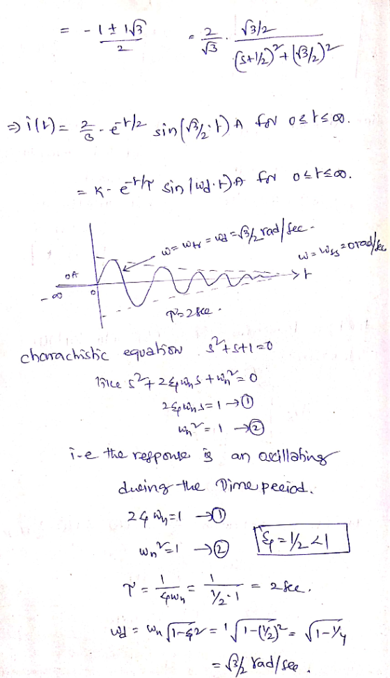
3. Natural response, for ? > 0 of a series R-L-C circuit has R = 1 Ω , L = 1 H and C = 1 F. The initial capacitor voltage is 4 V, and initial inductor current is zero. The series current is i.
(i) Draw the time domain circuit.
(ii) Draw the Laplace transform domain circuit.
(iii) From (ii), determine Io =Io (s) (iv) From (iii), determine ?? = ??(?) for t > 0
Homework Answers

Add Answer to:
3. Natural response, for ? > 0 of a series R-L-C circuit has
R = 1...
Function Generatr Inductor Model Ra R, Figure 1 Series RLC Circuit Preliminary This laboratory wi...
 Function Generatr Inductor Model Ra R, Figure 1 Series RLC Circuit Preliminary This laboratory will demonstrate how varying resistance changes the natural response of a series RLC circuit (Fig. 1). The function generator is modeled as an ideal voltage source v(t) 5 u() V in series with source resistance Rs-50Q. After measurements using an LCR meter, the inductor is modeled as an ideal L 90 mH inductor in series with resistance RL-20Q. The capacitance is C-0.22 μF. 1) Calculate the...
use laplace transform clearly and partial fractions clearly In a practical experiment a sinusoidal input is...
 use
laplace transform clearly and partial fractions clearly
In a practical experiment a sinusoidal input is applied at time t 0, to a series RC circuit, with all initial conditions being equal to zero. The resistor R-10 Ω and capacitance C-0.5uF (a)Draw the circuit in the s-domain. (b) Use the Laplace transforms to deduce in both s- domain and time domain:- (ii) (iii) The current flowing in the circuit and The voltage across the capacitor
use
laplace transform clearly and partial fractions clearly
In a practical experiment a sinusoidal input is applied at time t 0, to a series RC circuit, with all initial conditions being equal to zero. The resistor R-10 Ω and capacitance C-0.5uF (a)Draw the circuit in the s-domain. (b) Use the Laplace transforms to deduce in both s- domain and time domain:- (ii) (iii) The current flowing in the circuit and The voltage across the capacitor
1) (40 pts total) Solving and order ODE using Laplace Transforms: Consider a series RLC circuit...
 1) (40 pts total) Solving and order ODE using Laplace Transforms: Consider a series RLC circuit with resistor R, inductor L, and a capacitor C in series. The same current i(t) flows through R, L, and C. The voltage source v(t) is removed at t=0, but current continues to flow through the circuit for some time. We wish to find the natural response of this series RLC circuit, and find an equation for i(t). Using KVL and differentiating the equation...
The Natural Response of an RL Circuit In summary, to find the time constant of an...
 The Natural Response of an RL Circuit In summary, to find the time constant of an RL circuit, find the Thevenin equivalent resistance se Learning Goal: To analyze an RL circuit to determine the initial current through an inductor, the time constant, and the expression for the natural response of the inductor current, and to use the expression for the inductor current to find other circuit quantities, such as current, voltage, power, or energy. The natural response of an RL...
TEE301/05 Question 3 (20 marks) An RLC circuit with a 1V DC source is shown in...
 TEE301/05 Question 3 (20 marks) An RLC circuit with a 1V DC source is shown in Fig. 1: i(t) Vout - R-0.22 L-0.1 H C- 10 F Fig. 1 (a) List two properties of Laplace transform. Explain these two properties. [6 marks] (b) Assume that the initial inductor current is OA and initial capacitor voltage is 0.4 V 4 marks] (c) Determine the current, t) in time domain by performing inverse Laplace transform. [4 marks) determine the expression of the...
use R=1Ω, L=1H and C= 1/5 F Instead (c) In the circuit shown in Figure P2.61(c),...
 use R=1Ω, L=1H and C= 1/5 F Instead
(c) In the circuit shown in Figure P2.61(c), x(t) is the input voltage. The voltage y(t) across the capacitor is considered to be the system output wwww L 1H R=20 + y(t) x(t) C (c) Figure P2.61c (i) Determine the differential equation relating x(t) and y(t) (ii) Show that the homogeneous solution of the differential equation from part (i) has the forme "{K\ej2 + K2e"j2r}, and specify the value of a (iii...
use R=1Ω, L=1H and C= 1/5 F Instead
(c) In the circuit shown in Figure P2.61(c), x(t) is the input voltage. The voltage y(t) across the capacitor is considered to be the system output wwww L 1H R=20 + y(t) x(t) C (c) Figure P2.61c (i) Determine the differential equation relating x(t) and y(t) (ii) Show that the homogeneous solution of the differential equation from part (i) has the forme "{K\ej2 + K2e"j2r}, and specify the value of a (iii...
6. In a simple RCL series circuit with R = 100 Ω, C = 0.0004 F(farad),...
 6. In a simple RCL series circuit with R = 100 Ω, C = 0.0004 F(farad), and L-1 H (henry) and the impressed voltage v) 30. Find the charge Q) on the capacitor in the circuit at any time tif the initial current i(0) 2.A and the initial charge on the capacitor is 0(0)-0 C(coulomb) The Second Order ODE for RCL series circuit is given by where Qis the charge, and the current I =a- de dt
The circuit shown in Figure 3 below shows a R-L-C series circuit with components R= 50...
 The circuit shown in Figure 3 below shows a R-L-C series circuit with components R= 50 , L = 1 H, and C= 250 uF. This circuit is connected in series to an AC current source ( il ) where instantaneous current is given by it = 28.29 Sin (100t) A. B + VR- C + VC - D ).4C Current source Figure 3 (a) Draw the circuit diagram for this circuit and mark the impedances (3 marks) (b) What...
In a series circuit, suppose R=120Ω, L=220mH, C=0.60μF, V=75V, and ω=5550rad/s. Find the current amplitude I....
In a series circuit, suppose R=120Ω, L=220mH, C=0.60μF, V=75V, and ω=5550rad/s. Find the current amplitude I. Find the voltage amplitude across the resistor. Find the voltage amplitude across the inductor. Find the voltage amplitude across the capacitor.
A series L-R-C circuit is driven with AC voltage of amplitude Vin and frequency ω. Define...
 A series L-R-C circuit is driven with AC voltage of
amplitude Vin and frequency ω. Define Vout to be the amplitude of
the voltage across the capacitor. The resistance of the resistor is
R, the capacitance of the capacitor is C, and the inductance of the
inductor is L.(Figure 1)
What is the ratio VoutVin?
Express your answer in terms of either R, ω, L, and C or R, XL
=ωL, and XC =1ωC.
Vin c+ Vout
A series L-R-C circuit is driven with AC voltage of
amplitude Vin and frequency ω. Define Vout to be the amplitude of
the voltage across the capacitor. The resistance of the resistor is
R, the capacitance of the capacitor is C, and the inductance of the
inductor is L.(Figure 1)
What is the ratio VoutVin?
Express your answer in terms of either R, ω, L, and C or R, XL
=ωL, and XC =1ωC.
Vin c+ Vout
 Function Generatr Inductor Model Ra R, Figure 1 Series RLC Circuit Preliminary This laboratory will demonstrate how varying resistance changes the natural response of a series RLC circuit (Fig. 1). The function generator is modeled as an ideal voltage source v(t) 5 u() V in series with source resistance Rs-50Q. After measurements using an LCR meter, the inductor is modeled as an ideal L 90 mH inductor in series with resistance RL-20Q. The capacitance is C-0.22 μF. 1) Calculate the...
 use
laplace transform clearly and partial fractions clearly
In a practical experiment a sinusoidal input is applied at time t 0, to a series RC circuit, with all initial conditions being equal to zero. The resistor R-10 Ω and capacitance C-0.5uF (a)Draw the circuit in the s-domain. (b) Use the Laplace transforms to deduce in both s- domain and time domain:- (ii) (iii) The current flowing in the circuit and The voltage across the capacitor
use
laplace transform clearly and partial fractions clearly
In a practical experiment a sinusoidal input is applied at time t 0, to a series RC circuit, with all initial conditions being equal to zero. The resistor R-10 Ω and capacitance C-0.5uF (a)Draw the circuit in the s-domain. (b) Use the Laplace transforms to deduce in both s- domain and time domain:- (ii) (iii) The current flowing in the circuit and The voltage across the capacitor
 1) (40 pts total) Solving and order ODE using Laplace Transforms: Consider a series RLC circuit with resistor R, inductor L, and a capacitor C in series. The same current i(t) flows through R, L, and C. The voltage source v(t) is removed at t=0, but current continues to flow through the circuit for some time. We wish to find the natural response of this series RLC circuit, and find an equation for i(t). Using KVL and differentiating the equation...
 The Natural Response of an RL Circuit In summary, to find the time constant of an RL circuit, find the Thevenin equivalent resistance se Learning Goal: To analyze an RL circuit to determine the initial current through an inductor, the time constant, and the expression for the natural response of the inductor current, and to use the expression for the inductor current to find other circuit quantities, such as current, voltage, power, or energy. The natural response of an RL...
 TEE301/05 Question 3 (20 marks) An RLC circuit with a 1V DC source is shown in Fig. 1: i(t) Vout - R-0.22 L-0.1 H C- 10 F Fig. 1 (a) List two properties of Laplace transform. Explain these two properties. [6 marks] (b) Assume that the initial inductor current is OA and initial capacitor voltage is 0.4 V 4 marks] (c) Determine the current, t) in time domain by performing inverse Laplace transform. [4 marks) determine the expression of the...
 use R=1Ω, L=1H and C= 1/5 F Instead
(c) In the circuit shown in Figure P2.61(c), x(t) is the input voltage. The voltage y(t) across the capacitor is considered to be the system output wwww L 1H R=20 + y(t) x(t) C (c) Figure P2.61c (i) Determine the differential equation relating x(t) and y(t) (ii) Show that the homogeneous solution of the differential equation from part (i) has the forme "{K\ej2 + K2e"j2r}, and specify the value of a (iii...
use R=1Ω, L=1H and C= 1/5 F Instead
(c) In the circuit shown in Figure P2.61(c), x(t) is the input voltage. The voltage y(t) across the capacitor is considered to be the system output wwww L 1H R=20 + y(t) x(t) C (c) Figure P2.61c (i) Determine the differential equation relating x(t) and y(t) (ii) Show that the homogeneous solution of the differential equation from part (i) has the forme "{K\ej2 + K2e"j2r}, and specify the value of a (iii...
 6. In a simple RCL series circuit with R = 100 Ω, C = 0.0004 F(farad), and L-1 H (henry) and the impressed voltage v) 30. Find the charge Q) on the capacitor in the circuit at any time tif the initial current i(0) 2.A and the initial charge on the capacitor is 0(0)-0 C(coulomb) The Second Order ODE for RCL series circuit is given by where Qis the charge, and the current I =a- de dt
 The circuit shown in Figure 3 below shows a R-L-C series circuit with components R= 50 , L = 1 H, and C= 250 uF. This circuit is connected in series to an AC current source ( il ) where instantaneous current is given by it = 28.29 Sin (100t) A. B + VR- C + VC - D ).4C Current source Figure 3 (a) Draw the circuit diagram for this circuit and mark the impedances (3 marks) (b) What...
 A series L-R-C circuit is driven with AC voltage of
amplitude Vin and frequency ω. Define Vout to be the amplitude of
the voltage across the capacitor. The resistance of the resistor is
R, the capacitance of the capacitor is C, and the inductance of the
inductor is L.(Figure 1)
What is the ratio VoutVin?
Express your answer in terms of either R, ω, L, and C or R, XL
=ωL, and XC =1ωC.
Vin c+ Vout
A series L-R-C circuit is driven with AC voltage of
amplitude Vin and frequency ω. Define Vout to be the amplitude of
the voltage across the capacitor. The resistance of the resistor is
R, the capacitance of the capacitor is C, and the inductance of the
inductor is L.(Figure 1)
What is the ratio VoutVin?
Express your answer in terms of either R, ω, L, and C or R, XL
=ωL, and XC =1ωC.
Vin c+ Vout
Most questions answered within 3 hours.
-
Given input { 66, 28, 43, 29, 44, 69, 19 } and a hash function
h(x)...
asked 1 minute ago -
A pebble with mass m is thrown straight up with an initial speed
v0 so that...
asked 5 minutes ago -
Let X be a discrete random variable that follows a
binomial distribution with n = 11...
asked 14 minutes ago -
The equilibrium constant, K, for the following reaction is
1.29×10⁻² at 600
K.
COCl2(g) --->
CO(g)...
asked 27 minutes ago -
It is known that 72% of people have a favorable opinion of their
local police force....
asked 30 minutes ago -
A vertical straight wire carrying an upward 26-A current exerts
an attractive force per unit length...
asked 43 minutes ago -
For the purposes of this assignment, you are to choose an
adaptive trait common to more...
asked 51 minutes ago -
Two identical flutes can play middle C (262 Hz) at 20◦C. How
many beats per second...
asked 59 minutes ago -
Potassium phosphate and calcium chloride react in a double
replacement reaction. To produce 1.0 moles of...
asked 54 minutes ago -
Sparky, Co. purchased land as a factory site for $600,000.
Sparky paid $42,000 to tear down...
asked 1 hour ago -
A Chi-square distribution with 14 degrees of freedom is a
correct model for
Question 8 options:...
asked 1 hour ago -
In a group of 45 mice, there are 10 that have a certain genetic
character. suppose...
asked 1 hour ago