
Homework Answers

Add Answer to:
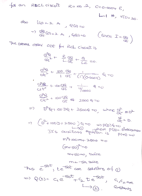
6. In a simple RCL series circuit with R = 100 Ω, C = 0.0004 F(farad),...
1 2 9. The diagram below is an RCL circuit with R = 10 ohms, C...
 1 2 9. The diagram below is an RCL circuit with R = 10 ohms, C = 10-2farad, L henry, and V = 12 volts. The switch is closed at time t = 0. Assume that the initial current i(0) = 0 and the initial charge on the capacitor Q(0) = 0 . Find the current i = i(t) in the circuit if i satisfies the equation and, according to Kirchhoff's law, ai lezo = R di d2i dt2 +...
A circuit comprises a 2 henry inductor, a 1/32 farad capacitor, no resistor, and a voltage...
A circuit comprises a 2 henry inductor, a 1/32 farad capacitor, no resistor, and a voltage source of 128 sin 4t volts. NOTE: initial conditions are not needed to do this problem. (a) Write the governing equation (ODE) for q(t). Do NOT solve the ODE. (b) Without solving the ODE for q(t), determine the natural frequency of the circuit (with units). (c) Will the circuit undergo pure resonance? Clearly explain why or why not.
Find the charge q(t) on the capacitor and the current i(t) in the given LRC-series circuit 1-1 h,...
 Find the charge q(t) on the capacitor and the current i(t) in the given LRC-series circuit 1-1 h, R-100 Ω, C-0.0004 f, E(t)-20 V, q(0)-0 C, i(0) 3 A Find the maximum charge on the capacitor. (Round your answer to four decimal places.) Need Help? Read It Talk to a Tutor
Find the charge q(t) on the capacitor and the current i(t) in the given LRC-series circuit 1-1 h, R-100 Ω, C-0.0004 f, E(t)-20 V, q(0)-0 C, i(0) 3 A...
Find the charge q(t) on the capacitor and the current i(t) in the given LRC-series circuit 1-1 h, R-100 Ω, C-0.0004 f, E(t)-20 V, q(0)-0 C, i(0) 3 A Find the maximum charge on the capacitor. (Round your answer to four decimal places.) Need Help? Read It Talk to a Tutor
Find the charge q(t) on the capacitor and the current i(t) in the given LRC-series circuit 1-1 h, R-100 Ω, C-0.0004 f, E(t)-20 V, q(0)-0 C, i(0) 3 A...
A 40-volt electromotive force is applied to an LR-series circuit in which the inductance is 0.1
 A 40-volt electromotive force is applied to an LR-series circuit in which the inductance is 0.1 henry and the resistance is 60 ohms. Find the current i(t) if i(0) = 0. Determine the current as t → ∞.A 100 volt electromotive force is applied to an RC series circuit in which the resistance is 500 ohms and the capacitance is 10-4 farad. Find the charge t on the capacitor if q(0) = 0.
Question 2 (5 marks) In a single-loop LRC-series circuit, Kirchhoffs second law states that the sum of voltage drop...
 Question 2 (5 marks) In a single-loop LRC-series circuit, Kirchhoffs second law states that the sum of voltage drops across an inductor, capacitor, and resistor is equal to the impressed voltage E(t). Use the Laplace trans form to find the charge on the capacitor in an RLC-series circuit at t 10 s when Lh, R 20, C = f, q(0) = 2 C, i (0) = 0 A, E(t) (10 0 st<5 t 5
Question 2 (5 marks) In a...
Question 2 (5 marks) In a single-loop LRC-series circuit, Kirchhoffs second law states that the sum of voltage drops across an inductor, capacitor, and resistor is equal to the impressed voltage E(t). Use the Laplace trans form to find the charge on the capacitor in an RLC-series circuit at t 10 s when Lh, R 20, C = f, q(0) = 2 C, i (0) = 0 A, E(t) (10 0 st<5 t 5
Question 2 (5 marks) In a...
3. Natural response, for ? > 0 of a series R-L-C circuit has R = 1...
3. Natural response, for ? > 0 of a series R-L-C circuit has R = 1 Ω , L = 1 H and C = 1 F. The initial capacitor voltage is 4 V, and initial inductor current is zero. The series current is i. (i) Draw the time domain circuit. (ii) Draw the Laplace transform domain circuit. (iii) From (ii), determine Io =Io (s) (iv) From (iii), determine ?? = ??(?) for t > 0
Learning Goal: To understand the dynamics of a series R-C circuit. Consider a series circuit containing...
 Learning Goal: To understand the dynamics of a series R-C circuit. Consider a series circuit containing a resistor of resistance R and a capacitor of capacitance C connected to a source of EMF ε with negligible internal resistance. The wires are also assumed to have zero resistance. Initially, the switch is open and the capacitor discharged. (Figure 1)Let us try to understand the processes that take place after the switch is closed. The charge of the capacitor, the current in...
Consider the simple series RLC circuit shown in figure below, the circuit has the following parameters,...
 Consider the simple series RLC circuit shown in figure below, the circuit has the following parameters, R=12, L = 0.2 Henry, and C = 0.05 Farad, R 1000 Vs The system is governed by the following equations: V = VR + V + V VR = IR V = Vc S(t)dt Or I = CM Construct a Simulink model for this system such that the input is the supply voltage Vs and the output is the voltage across the resistor...
Consider a Sinusoidally Driven LC Electrical Circuit, which Contains an Electric Potential Oscill...
 Consider a Sinusoidally Driven LC Electrical Circuit, which Contains an Electric Potential Oscillator, E E, cos(or), an Inductor, L, and a Capacitor, C. Note that an Oscillating Charge,g).Forms on the Capacitor Plates, as well as an Oscillating Current, I(). throughout the Circuit, which is Associated with the Driven Frequency, ω , as Shown. 1. 1(6) gt) E(r) Recall that the Electric Potential Over an Inductor is Given by E , and the dl dr Electric Potential Over a Capacitor is...
 1 2 9. The diagram below is an RCL circuit with R = 10 ohms, C = 10-2farad, L henry, and V = 12 volts. The switch is closed at time t = 0. Assume that the initial current i(0) = 0 and the initial charge on the capacitor Q(0) = 0 . Find the current i = i(t) in the circuit if i satisfies the equation and, according to Kirchhoff's law, ai lezo = R di d2i dt2 +...
 1 2 9. The diagram below is an RCL circuit with R = 10 ohms, C = 10-2farad, L henry, and V = 12 volts. The switch is closed at time t = 0. Assume that the initial current i(0) = 0 and the initial charge on the capacitor Q(0) = 0 . Find the current i = i(t) in the circuit if i satisfies the equation and, according to Kirchhoff's law, ai lezo = R di d2i dt2 +...
 Find the charge q(t) on the capacitor and the current i(t) in the given LRC-series circuit 1-1 h, R-100 Ω, C-0.0004 f, E(t)-20 V, q(0)-0 C, i(0) 3 A Find the maximum charge on the capacitor. (Round your answer to four decimal places.) Need Help? Read It Talk to a Tutor
Find the charge q(t) on the capacitor and the current i(t) in the given LRC-series circuit 1-1 h, R-100 Ω, C-0.0004 f, E(t)-20 V, q(0)-0 C, i(0) 3 A...
Find the charge q(t) on the capacitor and the current i(t) in the given LRC-series circuit 1-1 h, R-100 Ω, C-0.0004 f, E(t)-20 V, q(0)-0 C, i(0) 3 A Find the maximum charge on the capacitor. (Round your answer to four decimal places.) Need Help? Read It Talk to a Tutor
Find the charge q(t) on the capacitor and the current i(t) in the given LRC-series circuit 1-1 h, R-100 Ω, C-0.0004 f, E(t)-20 V, q(0)-0 C, i(0) 3 A...
 Question 2 (5 marks) In a single-loop LRC-series circuit, Kirchhoffs second law states that the sum of voltage drops across an inductor, capacitor, and resistor is equal to the impressed voltage E(t). Use the Laplace trans form to find the charge on the capacitor in an RLC-series circuit at t 10 s when Lh, R 20, C = f, q(0) = 2 C, i (0) = 0 A, E(t) (10 0 st<5 t 5
Question 2 (5 marks) In a...
Question 2 (5 marks) In a single-loop LRC-series circuit, Kirchhoffs second law states that the sum of voltage drops across an inductor, capacitor, and resistor is equal to the impressed voltage E(t). Use the Laplace trans form to find the charge on the capacitor in an RLC-series circuit at t 10 s when Lh, R 20, C = f, q(0) = 2 C, i (0) = 0 A, E(t) (10 0 st<5 t 5
Question 2 (5 marks) In a...
 Consider the simple series RLC circuit shown in figure below, the circuit has the following parameters, R=12, L = 0.2 Henry, and C = 0.05 Farad, R 1000 Vs The system is governed by the following equations: V = VR + V + V VR = IR V = Vc S(t)dt Or I = CM Construct a Simulink model for this system such that the input is the supply voltage Vs and the output is the voltage across the resistor...
 Consider a Sinusoidally Driven LC Electrical Circuit, which Contains an Electric Potential Oscillator, E E, cos(or), an Inductor, L, and a Capacitor, C. Note that an Oscillating Charge,g).Forms on the Capacitor Plates, as well as an Oscillating Current, I(). throughout the Circuit, which is Associated with the Driven Frequency, ω , as Shown. 1. 1(6) gt) E(r) Recall that the Electric Potential Over an Inductor is Given by E , and the dl dr Electric Potential Over a Capacitor is...
Most questions answered within 3 hours.
-
A 0.25μF capacitor is charged to 50 V . It is then connected in
series with...
asked 5 minutes ago -
Calculate the current, I, through the batteries for:
- a 2-bulb parallel circuit
- How does...
asked 6 minutes ago -
Choose the sentence that uses correct punctuation.
1a. The prefatory parts of a report include the...
asked 12 minutes ago -
For the element arsenic, which one of the following sets of
quantum numbers could not apply...
asked 21 minutes ago -
Compare and contrast the architectures of 3 types of ADCs:
Flash, SAR, and pipelined. Use the...
asked 23 minutes ago -
Given P(A) = 0.40, P(B) = 0.50, P(A ∩ B) = 0.15. Which of the
following...
asked 27 minutes ago -
Explain changes in workforce participation for women with
children. What legislation exists related to work and...
asked 29 minutes ago -
How high must a pointed arch be if it is to span a
space 4.2 m...
asked 34 minutes ago -
A housepainter who weighs 750 N stands 0.6 m from one end of a
2.0 m...
asked 36 minutes ago -
Implement Singly Linked List detectLoop in Java.
It would check whether the linked list contains a...
asked 39 minutes ago -
A small mailbag is released from a helicopter that is descending
steadily at 2.10 m/s.
After...
asked 40 minutes ago -
Write a C – program that calls a user-defined function from
within main() that determines the...
asked 43 minutes ago