 strength of material
engineering of mechanical
please solve this question
Homework Answers


Add Answer to:
strength of material
engineering of mechanical
please solve this question
50 km 03: The pipe shown...
Question A-36 steel pipe with an outer diameter of 100 mm and an inner diameter of...
 Question A-36 steel pipe with an outer diameter of 100 mm and an inner diameter of 80 mm subjected to loadings shown in Figure 1. The pipe is rigidly fixed at B and P - 150 kN. Given the yield stress, Oy -250 MPa and factor of safety, F.S. - 1.5 is used against yielding on this entire pipe. (a) For the stress state at the surface, construct the Mohr circle and determine: (1) the total stresses at surface of...
Question A-36 steel pipe with an outer diameter of 100 mm and an inner diameter of...
 Question A-36 steel pipe with an outer diameter of 100 mm and an inner diameter of 80 mm subjected to loadings shown in Figure 1. The pipe is rigidly fixed at B and P = 150 kN. Given the yield stress, Oy=250 MPa and factor of safety, F.S. = 1.5 is used against yielding on this entire pipe. (a) For the stress state at the surface, construct the Mohr circle and determine: (1) the total stresses at surface of the...
A pipe with an outside diameter of 175 mm and a wall thickness of 6 mm...
 A pipe with an outside diameter of 175 mm and a wall thickness of 6 mm is subjected to the loadings shown in the figure below. Р. H For this analysis, use the following values: Distances, Loads, and Moments. a = 400 mm Px = 40.5 kN Py = 68.5 kN T = 35 kN-m (a) Calculate the maximum in-plane shear stress Tmax at point Hon the outer surface of the pipe if there is no internal pressure (i.e.,p-OkPa). (Note:...
A pipe with an outside diameter of 150 mm and a wall thickness of 5 mm...
 A pipe with an outside diameter of 150 mm and a wall thickness of 5 mm is subjected to the loadings shown in the figure below. P PO a For this analysis, use the following values: Distances, Loads, and Moments. a = 450 mm Px = 11.5 kN Py = 25.5 kN T = 15 kN-m (a) Calculate the maximum in-plane shear stress Tmax at point Hon the outer surface of the pipe if there is no internal pressure (i.e.,...
3. The propeller shaft of the tugboat is subjected to the compressive force and torque shown....
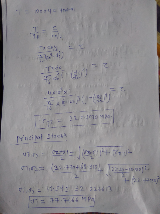
 3. The propeller shaft of the tugboat is subjected to the compressive force and torque shown. The shaft has an inner diameter of 125 mm and an outer diameter of 175 mm. (20 pts) 0410 KN 2 kNm Determine the following at point A located on the outer surface: avg. TMIP, 8s Principal stresses and Op c Draw Mohr's circle d Draw principal stress and maximum in plane shear stress elements
I need help with part B thank you A pipe with an outside diameter of 150...
 I need help with part B thank you
A pipe with an outside diameter of 150 mm and a wall thickness of 5 mm is subjected to the loadings shown in the figure below. P PO a For this analysis, use the following values: Distances, Loads, and Moments. a = 450 mm Px = 11.5 kN Py = 25.5 kN T = 15 kN-m (a) Calculate the maximum in-plane shear stress Tmax at point Hon the outer surface of the...
I need help with part B thank you
A pipe with an outside diameter of 150 mm and a wall thickness of 5 mm is subjected to the loadings shown in the figure below. P PO a For this analysis, use the following values: Distances, Loads, and Moments. a = 450 mm Px = 11.5 kN Py = 25.5 kN T = 15 kN-m (a) Calculate the maximum in-plane shear stress Tmax at point Hon the outer surface of the...
above provided question with answer... So using that solve below question so solve this question....I'm provided...
 above provided question with
answer...
So using that solve below question
so solve this question....I'm
provided sample question with answer too
Same process values are changed...
I will give positive rating
(b) Calculate the maximum in-plane shear stress Imax on the outer surface of the pipe at point kif there is an internal pressure of 3600 kPa inside the pipe. (Note: Enter the absolute value here.) Tax for point- MPa For this analysis, use the following values: Distances, Loads, and...
above provided question with
answer...
So using that solve below question
so solve this question....I'm
provided sample question with answer too
Same process values are changed...
I will give positive rating
(b) Calculate the maximum in-plane shear stress Imax on the outer surface of the pipe at point kif there is an internal pressure of 3600 kPa inside the pipe. (Note: Enter the absolute value here.) Tax for point- MPa For this analysis, use the following values: Distances, Loads, and...
please solve 7 of 10 The thin walled pipe has an inner diameter of 0.5 in...
 please solve
7 of 10 The thin walled pipe has an inner diameter of 0.5 in and a thickness of 0 025 in Review Part A If it is subjected to an internal pressure of 434 pesi and the axial tension and forsional loadings shown, determine the principal stress at a point on the surface of the pipe gure 1) Enter your answers numerically separated by a comma. Figure < 1011 > 30 AED vec RO ? 0,09= Submit Request...
please solve
7 of 10 The thin walled pipe has an inner diameter of 0.5 in and a thickness of 0 025 in Review Part A If it is subjected to an internal pressure of 434 pesi and the axial tension and forsional loadings shown, determine the principal stress at a point on the surface of the pipe gure 1) Enter your answers numerically separated by a comma. Figure < 1011 > 30 AED vec RO ? 0,09= Submit Request...
The JT100 horizontal directional drilling machine applies 220 hp and rotates drill pipe at 100 rp...
 The JT100 horizontal directional drilling machine applies 220 hp and rotates drill pipe at 100 rpm. During the drilling process, a drill pipe is subjected to the following axial and bending loads 30.0 Axial load, P, of 100 kips 0.70 ft-kips bending load, M, in the y-z plane at 30 degrees from the vertical axis The drill pipe, which is made of AISI 4130 steel, has the following dimensions and material properties (Ref. MIL-HDBK-5J, Table 2.3.1.0(c1)) » Length, L 177-in...
The assembly consists of two sections of galvanized steel pipe connected together using a reducing coupling...
 The assembly consists of two sections of galvanized steel pipe connected together using a reducing coupling at B. The smaller pipe has an outer diameter of 18.75 mm and an inner diameter of 17 mm, whereas the larger pipe has an outer diameter of 25 mm and an inner diameter of 21.5 mm. The pipe is tightly secured to the wall at C. The couple shown is applied to the handles of the wrench. (Figure 1) Part A Determine the...
 Question A-36 steel pipe with an outer diameter of 100 mm and an inner diameter of 80 mm subjected to loadings shown in Figure 1. The pipe is rigidly fixed at B and P - 150 kN. Given the yield stress, Oy -250 MPa and factor of safety, F.S. - 1.5 is used against yielding on this entire pipe. (a) For the stress state at the surface, construct the Mohr circle and determine: (1) the total stresses at surface of...
 Question A-36 steel pipe with an outer diameter of 100 mm and an inner diameter of 80 mm subjected to loadings shown in Figure 1. The pipe is rigidly fixed at B and P = 150 kN. Given the yield stress, Oy=250 MPa and factor of safety, F.S. = 1.5 is used against yielding on this entire pipe. (a) For the stress state at the surface, construct the Mohr circle and determine: (1) the total stresses at surface of the...
 A pipe with an outside diameter of 175 mm and a wall thickness of 6 mm is subjected to the loadings shown in the figure below. Р. H For this analysis, use the following values: Distances, Loads, and Moments. a = 400 mm Px = 40.5 kN Py = 68.5 kN T = 35 kN-m (a) Calculate the maximum in-plane shear stress Tmax at point Hon the outer surface of the pipe if there is no internal pressure (i.e.,p-OkPa). (Note:...
 A pipe with an outside diameter of 150 mm and a wall thickness of 5 mm is subjected to the loadings shown in the figure below. P PO a For this analysis, use the following values: Distances, Loads, and Moments. a = 450 mm Px = 11.5 kN Py = 25.5 kN T = 15 kN-m (a) Calculate the maximum in-plane shear stress Tmax at point Hon the outer surface of the pipe if there is no internal pressure (i.e.,...
 3. The propeller shaft of the tugboat is subjected to the compressive force and torque shown. The shaft has an inner diameter of 125 mm and an outer diameter of 175 mm. (20 pts) 0410 KN 2 kNm Determine the following at point A located on the outer surface: avg. TMIP, 8s Principal stresses and Op c Draw Mohr's circle d Draw principal stress and maximum in plane shear stress elements
 I need help with part B thank you
A pipe with an outside diameter of 150 mm and a wall thickness of 5 mm is subjected to the loadings shown in the figure below. P PO a For this analysis, use the following values: Distances, Loads, and Moments. a = 450 mm Px = 11.5 kN Py = 25.5 kN T = 15 kN-m (a) Calculate the maximum in-plane shear stress Tmax at point Hon the outer surface of the...
I need help with part B thank you
A pipe with an outside diameter of 150 mm and a wall thickness of 5 mm is subjected to the loadings shown in the figure below. P PO a For this analysis, use the following values: Distances, Loads, and Moments. a = 450 mm Px = 11.5 kN Py = 25.5 kN T = 15 kN-m (a) Calculate the maximum in-plane shear stress Tmax at point Hon the outer surface of the...
 above provided question with
answer...
So using that solve below question
so solve this question....I'm
provided sample question with answer too
Same process values are changed...
I will give positive rating
(b) Calculate the maximum in-plane shear stress Imax on the outer surface of the pipe at point kif there is an internal pressure of 3600 kPa inside the pipe. (Note: Enter the absolute value here.) Tax for point- MPa For this analysis, use the following values: Distances, Loads, and...
above provided question with
answer...
So using that solve below question
so solve this question....I'm
provided sample question with answer too
Same process values are changed...
I will give positive rating
(b) Calculate the maximum in-plane shear stress Imax on the outer surface of the pipe at point kif there is an internal pressure of 3600 kPa inside the pipe. (Note: Enter the absolute value here.) Tax for point- MPa For this analysis, use the following values: Distances, Loads, and...
 please solve
7 of 10 The thin walled pipe has an inner diameter of 0.5 in and a thickness of 0 025 in Review Part A If it is subjected to an internal pressure of 434 pesi and the axial tension and forsional loadings shown, determine the principal stress at a point on the surface of the pipe gure 1) Enter your answers numerically separated by a comma. Figure < 1011 > 30 AED vec RO ? 0,09= Submit Request...
please solve
7 of 10 The thin walled pipe has an inner diameter of 0.5 in and a thickness of 0 025 in Review Part A If it is subjected to an internal pressure of 434 pesi and the axial tension and forsional loadings shown, determine the principal stress at a point on the surface of the pipe gure 1) Enter your answers numerically separated by a comma. Figure < 1011 > 30 AED vec RO ? 0,09= Submit Request...
 The JT100 horizontal directional drilling machine applies 220 hp and rotates drill pipe at 100 rpm. During the drilling process, a drill pipe is subjected to the following axial and bending loads 30.0 Axial load, P, of 100 kips 0.70 ft-kips bending load, M, in the y-z plane at 30 degrees from the vertical axis The drill pipe, which is made of AISI 4130 steel, has the following dimensions and material properties (Ref. MIL-HDBK-5J, Table 2.3.1.0(c1)) » Length, L 177-in...
 The assembly consists of two sections of galvanized steel pipe connected together using a reducing coupling at B. The smaller pipe has an outer diameter of 18.75 mm and an inner diameter of 17 mm, whereas the larger pipe has an outer diameter of 25 mm and an inner diameter of 21.5 mm. The pipe is tightly secured to the wall at C. The couple shown is applied to the handles of the wrench. (Figure 1) Part A Determine the...
Most questions answered within 3 hours.
-
If 5.70 g of potassium react with water, how many grams of
hydrogen gas, H2, are...
asked 4 minutes ago -
How many moles of CO2 and H2O will be
produced by combustion analysis of 0.010 mol...
asked 2 minutes ago -
Tennis champion Maria Sharapova is capable of serving a tennis
ball at 126 mph.
b) What...
asked 10 minutes ago -
The electric potential V in the space between the plates of a
given vacuum tube is...
asked 19 minutes ago -
The Hydroboration-Oxidation of an Alkene to Yield 1-Octanol.
1-octene to 1-octanol using BH3-THF
What might be...
asked 24 minutes ago -
You draw and keep a single bill from a hat that contains a
$11, $55, $20...
asked 41 minutes ago -
Write a Java program that has the following methods:
findSum - a method that takes in...
asked 42 minutes ago -
A coffee cup calorimeter initially contains 135g of water at
22.0oC. Calcium chloride (21.0g) at the...
asked 46 minutes ago -
A patient is having a magnetic resonance imaging scan (an MRI)
and has neglected to remove...
asked 48 minutes ago -
A student takes a multiple-choice test that has 10 questions.
Each question has two choices. The...
asked 1 hour ago -
Willie Keeler has a lifetime batting average of 0.341. Assume
that Willie Keeler came to bat...
asked 1 hour ago -
Which of the following has the highest boiling point?
A) 0.5m NaCl
B) 0.5m C6H12O6
C)...
asked 1 hour ago