
Homework Answers
Add Answer to:
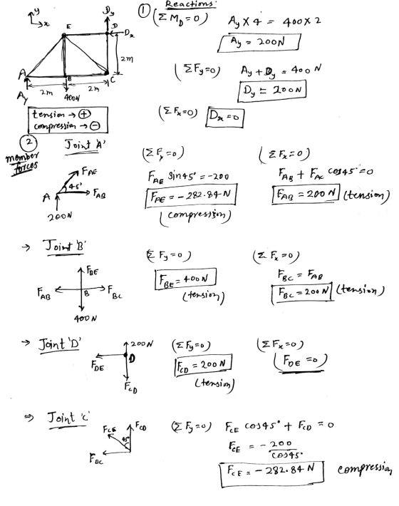
For the truss shown below, 1. Draw a free body diagram and determine the reactions at...
Statics problems Question A2 The plane truss shown in Figure A2 is supported at points A and J. -30° and the external loads are Fi 1.5 kN and F 3 kN. Draw the free body diagram of the truss. D...
 Statics problems
Question A2 The plane truss shown in Figure A2 is supported at points A and J. -30° and the external loads are Fi 1.5 kN and F 3 kN. Draw the free body diagram of the truss. Determine all the reactions at the supports or, if this is not possible, explain why. a) Calculate the internal forces in members CF, EH, GH and HI, stating whether they are in tension or compression. b) (12) Are members CF and...
Statics problems
Question A2 The plane truss shown in Figure A2 is supported at points A and J. -30° and the external loads are Fi 1.5 kN and F 3 kN. Draw the free body diagram of the truss. Determine all the reactions at the supports or, if this is not possible, explain why. a) Calculate the internal forces in members CF, EH, GH and HI, stating whether they are in tension or compression. b) (12) Are members CF and...
Final Exam 2. Analyze the truss shown below: (50 Points) a. Solve for the reactions at...
 Final Exam 2. Analyze the truss shown below: (50 Points) a. Solve for the reactions at supports A and D b. Determine the force developed in members FE, EB, and BC of the truss, and state if these members are in tension or compression. Use the method of sections, c. Draw a free body diagram (FBD) of: i. The entire truss, without its supports ii. The truss section after cutting it iii. Any joint that you solve. m 1 m...
Given: The Truss and loading shown in the diagram below Find: The reactions and forces in...
 Given: The Truss and loading shown in the diagram below Find: The reactions and forces in the members. Draw a Free Body Diagram clearly showing the reactions. List the member forces in the table including indicating if they are Tension or Compression. 500 lb Reactions Force Ay BX 4ft Member Force ft 3 ft 3ft
In the truss shown in the figure: 1. Determine the support reactions at supports A and...
 In the truss shown in the figure: 1. Determine the support reactions at supports A and F. (10 points) 2. Determine the force in members BC, IC, and IH of the truss using method of joints. Explain and justify if the members are in tension or compression. (20 points) 3. Draw FBD for each step of 1 and 2. (10 points) 60KN 40 kN -2 m -2 m -2 m E D 1.5 m F с O -30 kN H...
2. (a) Draw a free body diagram for member ABC shown below. (b) Determine the reactions...
 2. (a) Draw a free body diagram for member ABC shown below. (b) Determine the reactions at the supports A and C. P = 10 kN and a = 1 m. Begin your solution on this page 30
beam problem QUESTION 6: Draw the free body diagram of the beam shown below and determine...
 beam problem
QUESTION 6: Draw the free body diagram of the beam shown below and determine the reactions and formulate the shear-force and bending moment equations for the beam. Sketch the shear and moment diagrams: Type your answers and intermediate calculations on the screen on the blackboard 400 N 100 N/m A 4 m 4 m
beam problem
QUESTION 6: Draw the free body diagram of the beam shown below and determine the reactions and formulate the shear-force and bending moment equations for the beam. Sketch the shear and moment diagrams: Type your answers and intermediate calculations on the screen on the blackboard 400 N 100 N/m A 4 m 4 m
draw free body diagram, draw coordinate system, isolate object from its supports , add applied forces...
 draw free body diagram, draw coordinate system,
isolate object from its supports , add applied forces and body
force to object , determine known and unknown variables , resolve
force vectors into components , write the equilibrium equations ,
choose points about which moments rotate and show + direction ,
substitute values for the variables and solve for unknowns
rthe trusses shown below, neglect self-weight, and do the following: (a) Draw a free body diagram and solve for the reactions....
draw free body diagram, draw coordinate system,
isolate object from its supports , add applied forces and body
force to object , determine known and unknown variables , resolve
force vectors into components , write the equilibrium equations ,
choose points about which moments rotate and show + direction ,
substitute values for the variables and solve for unknowns
rthe trusses shown below, neglect self-weight, and do the following: (a) Draw a free body diagram and solve for the reactions....
Determine the force in members EL and LM of the truss and state if the members...
 Determine the force in members EL and LM of the truss and state if the members are in tension or compression. (Draw the free-body diagrams separately. Reaction forces and moments cannot be shown on the original figure.) 3@1m = 3m 41 m = 4 m 500 N 500N
Draw the Free Body Diagram of the beam. Determine the reactions at the supports A and...
 Draw the Free Body Diagram of the beam. Determine the reactions at the supports A and D. 5ft - 3ft-
Problem 1 Determine the reactions at the supports and the force in all the members of...
 Problem 1 Determine the reactions at the supports and the force in all the members of the truss, indicate whether the force is in tension or compression. The values shown apply. Drawing Not to Scale P1 T . . . a | 4 m | P1 | 2,000 N 5 m P2 4,000 N C 3 m нь
 Statics problems
Question A2 The plane truss shown in Figure A2 is supported at points A and J. -30° and the external loads are Fi 1.5 kN and F 3 kN. Draw the free body diagram of the truss. Determine all the reactions at the supports or, if this is not possible, explain why. a) Calculate the internal forces in members CF, EH, GH and HI, stating whether they are in tension or compression. b) (12) Are members CF and...
Statics problems
Question A2 The plane truss shown in Figure A2 is supported at points A and J. -30° and the external loads are Fi 1.5 kN and F 3 kN. Draw the free body diagram of the truss. Determine all the reactions at the supports or, if this is not possible, explain why. a) Calculate the internal forces in members CF, EH, GH and HI, stating whether they are in tension or compression. b) (12) Are members CF and...
 Final Exam 2. Analyze the truss shown below: (50 Points) a. Solve for the reactions at supports A and D b. Determine the force developed in members FE, EB, and BC of the truss, and state if these members are in tension or compression. Use the method of sections, c. Draw a free body diagram (FBD) of: i. The entire truss, without its supports ii. The truss section after cutting it iii. Any joint that you solve. m 1 m...
 Given: The Truss and loading shown in the diagram below Find: The reactions and forces in the members. Draw a Free Body Diagram clearly showing the reactions. List the member forces in the table including indicating if they are Tension or Compression. 500 lb Reactions Force Ay BX 4ft Member Force ft 3 ft 3ft
 In the truss shown in the figure: 1. Determine the support reactions at supports A and F. (10 points) 2. Determine the force in members BC, IC, and IH of the truss using method of joints. Explain and justify if the members are in tension or compression. (20 points) 3. Draw FBD for each step of 1 and 2. (10 points) 60KN 40 kN -2 m -2 m -2 m E D 1.5 m F с O -30 kN H...
 2. (a) Draw a free body diagram for member ABC shown below. (b) Determine the reactions at the supports A and C. P = 10 kN and a = 1 m. Begin your solution on this page 30
 beam problem
QUESTION 6: Draw the free body diagram of the beam shown below and determine the reactions and formulate the shear-force and bending moment equations for the beam. Sketch the shear and moment diagrams: Type your answers and intermediate calculations on the screen on the blackboard 400 N 100 N/m A 4 m 4 m
beam problem
QUESTION 6: Draw the free body diagram of the beam shown below and determine the reactions and formulate the shear-force and bending moment equations for the beam. Sketch the shear and moment diagrams: Type your answers and intermediate calculations on the screen on the blackboard 400 N 100 N/m A 4 m 4 m
 draw free body diagram, draw coordinate system,
isolate object from its supports , add applied forces and body
force to object , determine known and unknown variables , resolve
force vectors into components , write the equilibrium equations ,
choose points about which moments rotate and show + direction ,
substitute values for the variables and solve for unknowns
rthe trusses shown below, neglect self-weight, and do the following: (a) Draw a free body diagram and solve for the reactions....
draw free body diagram, draw coordinate system,
isolate object from its supports , add applied forces and body
force to object , determine known and unknown variables , resolve
force vectors into components , write the equilibrium equations ,
choose points about which moments rotate and show + direction ,
substitute values for the variables and solve for unknowns
rthe trusses shown below, neglect self-weight, and do the following: (a) Draw a free body diagram and solve for the reactions....
 Determine the force in members EL and LM of the truss and state if the members are in tension or compression. (Draw the free-body diagrams separately. Reaction forces and moments cannot be shown on the original figure.) 3@1m = 3m 41 m = 4 m 500 N 500N
 Draw the Free Body Diagram of the beam. Determine the reactions at the supports A and D. 5ft - 3ft-
 Problem 1 Determine the reactions at the supports and the force in all the members of the truss, indicate whether the force is in tension or compression. The values shown apply. Drawing Not to Scale P1 T . . . a | 4 m | P1 | 2,000 N 5 m P2 4,000 N C 3 m нь
Most questions answered within 3 hours.
-
A gas tank is a vertical cylinder. It has a radius of 1m, a
height of...
asked 23 seconds from now -
Accent Software faces the following conditions. All of these
support Accent’s use of a market-penetration pricing...
asked 56 minutes ago -
A mathematically inclined friend emails you the following
instructions: "Meet me in the cafeteria the first...
asked 58 minutes ago -
A monopoly sells in two countries . The demand curves in the two
countries are p1...
asked 1 hour ago -
A .15kg rubber ball is bounced off a wall. Before hitting the
wall, the ball moves...
asked 2 hours ago -
A manufacturing company preparing to build a new plant is
considering three potential locations for it....
asked 2 hours ago -
B. If compound Y has approximately the same values of solubility
in toluene as compound X,...
asked 3 hours ago -
Oscar Inc. has inventory in Japan valued at 39,051,000 Yen one
year ago. One year ago...
asked 3 hours ago -
If Canada suffered from "fundamental disequilibrium," and its
government choose not to devalue its currency, a...
asked 3 hours ago -
4. How many input & output Key Value Pairs are passed into,
and emitted out of...
asked 3 hours ago -
Why would your heart not function well if constructed of
skeletal muscle? What is the particular...
asked 3 hours ago -
Please respond to this essay question in full essay form for
Chemistry 1102 Organic and Biochemistry:...
asked 3 hours ago