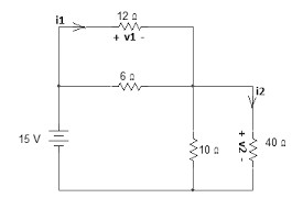
simulate the circuit measure V1 I1 and V2 I2 and attached screenshot
only used Proteus software
Homework Answers

V1=8.62volts
I1=0.72 amps
V2=6.16volts
I2=1.54 amps
Thank you
Add Answer to:
simulate the circuit measure V1 I1 and V2 I2 and
attached screenshot
only used Proteus software...
simulate the circuit in proteus software and measured voltage at node V1 V2 and v3 attached...
 simulate the circuit in proteus software and measured
voltage at node V1 V2 and v3 attached screenshot
used only proteus
10 ΚΩ V, 40 ΚΩ V, V. + 50 V 20 kΩ -80 V
simulate the circuit in proteus software and measured
voltage at node V1 V2 and v3 attached screenshot
used only proteus
10 ΚΩ V, 40 ΚΩ V, V. + 50 V 20 kΩ -80 V
(1 point) In the circuit below, i1 = -2 A, i2 = 8 A, and v1...
 (1 point) In the circuit
below, i1 = -2 A, i2 = 8 A, and v1 = -2 V. Use nodal analysis to
find vx and iy in the circuit below
i1 8Ω 15 Ω 36 Ω 2 iy y 14 Ω 20 Ω ν1 24 Ω 10 Ω i2 40 Ω 35 Ω 12 Ω 16 Ω 0.4Vx 2013 Paul Hummel CC BY NC SAΑ
(1 point) In the circuit
below, i1 = -2 A, i2 = 8 A, and v1 = -2 V. Use nodal analysis to
find vx and iy in the circuit below
i1 8Ω 15 Ω 36 Ω 2 iy y 14 Ω 20 Ω ν1 24 Ω 10 Ω i2 40 Ω 35 Ω 12 Ω 16 Ω 0.4Vx 2013 Paul Hummel CC BY NC SAΑ
1) In the following circuit, calculate i1, i2, v1, v2, and v3. moblern Set #1 In...
 1) In the following circuit, calculate i1, i2, v1, v2,
and v3.
moblern Set #1 In the So Lowin 3ง. 6 vous + ナ
1) In the following circuit, calculate i1, i2, v1, v2,
and v3.
moblern Set #1 In the So Lowin 3ง. 6 vous + ナ
In the circuit given below, determine the mesh currents i1(t) and i2(t). Let v1 = 14...
 In the circuit given below,
determine the mesh currents i1(t) and i2(t). Let v1 = 14 cos(4t) V
and v2 = 20 cos(4t – 30°) V. Please report your answer so the
magnitude is positive and all angles are in the range of negative
180 degrees to positive 180 degrees.
i1(t) = cos(4t
+ (˚)) A
i2(t) = cos(4t
+ ˚) A
In the circuit given below,
determine the mesh currents i1(t) and i2(t). Let v1 = 14 cos(4t) V
and v2 = 20 cos(4t – 30°) V. Please report your answer so the
magnitude is positive and all angles are in the range of negative
180 degrees to positive 180 degrees.
i1(t) = cos(4t
+ (˚)) A
i2(t) = cos(4t
+ ˚) A
For a circuit in series, why does V1+V2+V3=V total. For a circuit in parallel, why does...
For a circuit in series, why does V1+V2+V3=V total. For a circuit in parallel, why does I1+I2+I3= I total?
Question 3 Determine i1. i1 60 >20 i2 11 v2 12 V 111 20 40 330
 Question 3 Determine i1. i1 60 >20 i2 11 v2 12 V 111 20 40 330
Find I1, I2 and I3 for the circuit attached above. 30 Ω 20 V 1 13...
 Find I1, I2 and I3 for the circuit attached above.
30 Ω 20 V 1 13 10 V 112 20 Ω
Find I1, I2 and I3 for the circuit attached above.
30 Ω 20 V 1 13 10 V 112 20 Ω
Consider the electrical circuit shown above. It consists of two identical ideal batteries, V1 = V2...
 Consider the electrical
circuit shown above. It consists of two identical ideal batteries,
V1 = V2 = 24 V, and five resistors.
1)
Which of the following equations is not valid?
I2= I1 + I3
I2R2 + I3R3 +
V2 = 0
I1R1 + I2R2 -
V1 = 0
2)
Suppose the resistor R3 is shorted out, so that it
acts like a wire. What can we say about the current labelled
I1?
I1 is positive.
I1 is negative.
I1...
Consider the electrical
circuit shown above. It consists of two identical ideal batteries,
V1 = V2 = 24 V, and five resistors.
1)
Which of the following equations is not valid?
I2= I1 + I3
I2R2 + I3R3 +
V2 = 0
I1R1 + I2R2 -
V1 = 0
2)
Suppose the resistor R3 is shorted out, so that it
acts like a wire. What can we say about the current labelled
I1?
I1 is positive.
I1 is negative.
I1...
In the circuit below, i1 = -12 A, 12 = -15 A, and v1 = 11...
 In the circuit below, i1 = -12 A, 12 = -15 A, and v1 = 11 V. Use nodal analysis to find Vx and iy in the circuit below 2 VX 60 + W W 2Ω + 50 5 VX 40 W + - il | ly v1 703 4iy 3Ω W + 2014 Paul Hummel cc o BY NG SA Vx= V ly = A
2.3 Construct the circuit in Fig. 2.3 and measure the node voltage V1 and V2 and...
 2.3 Construct the circuit in Fig. 2.3 and measure the node voltage V1 and V2 and the current I going through from node 1->2 with reference ground A. If the ground moved to node B, again measure the V1, V2 and I. 10 V 402 11 4V 15V Dav 2002 B 500 DioΩ Fig. 2.3 Schematic diagram V V2 With Ref. A With Ref. A 2.4 Construct the circuit in Fig. 2.4. Using transient analysis tools to find out the...
 simulate the circuit in proteus software and measured
voltage at node V1 V2 and v3 attached screenshot
used only proteus
10 ΚΩ V, 40 ΚΩ V, V. + 50 V 20 kΩ -80 V
simulate the circuit in proteus software and measured
voltage at node V1 V2 and v3 attached screenshot
used only proteus
10 ΚΩ V, 40 ΚΩ V, V. + 50 V 20 kΩ -80 V
 (1 point) In the circuit
below, i1 = -2 A, i2 = 8 A, and v1 = -2 V. Use nodal analysis to
find vx and iy in the circuit below
i1 8Ω 15 Ω 36 Ω 2 iy y 14 Ω 20 Ω ν1 24 Ω 10 Ω i2 40 Ω 35 Ω 12 Ω 16 Ω 0.4Vx 2013 Paul Hummel CC BY NC SAΑ
(1 point) In the circuit
below, i1 = -2 A, i2 = 8 A, and v1 = -2 V. Use nodal analysis to
find vx and iy in the circuit below
i1 8Ω 15 Ω 36 Ω 2 iy y 14 Ω 20 Ω ν1 24 Ω 10 Ω i2 40 Ω 35 Ω 12 Ω 16 Ω 0.4Vx 2013 Paul Hummel CC BY NC SAΑ
 1) In the following circuit, calculate i1, i2, v1, v2,
and v3.
moblern Set #1 In the So Lowin 3ง. 6 vous + ナ
1) In the following circuit, calculate i1, i2, v1, v2,
and v3.
moblern Set #1 In the So Lowin 3ง. 6 vous + ナ
 In the circuit given below,
determine the mesh currents i1(t) and i2(t). Let v1 = 14 cos(4t) V
and v2 = 20 cos(4t – 30°) V. Please report your answer so the
magnitude is positive and all angles are in the range of negative
180 degrees to positive 180 degrees.
i1(t) = cos(4t
+ (˚)) A
i2(t) = cos(4t
+ ˚) A
In the circuit given below,
determine the mesh currents i1(t) and i2(t). Let v1 = 14 cos(4t) V
and v2 = 20 cos(4t – 30°) V. Please report your answer so the
magnitude is positive and all angles are in the range of negative
180 degrees to positive 180 degrees.
i1(t) = cos(4t
+ (˚)) A
i2(t) = cos(4t
+ ˚) A
 Question 3 Determine i1. i1 60 >20 i2 11 v2 12 V 111 20 40 330
 Find I1, I2 and I3 for the circuit attached above.
30 Ω 20 V 1 13 10 V 112 20 Ω
Find I1, I2 and I3 for the circuit attached above.
30 Ω 20 V 1 13 10 V 112 20 Ω
 Consider the electrical
circuit shown above. It consists of two identical ideal batteries,
V1 = V2 = 24 V, and five resistors.
1)
Which of the following equations is not valid?
I2= I1 + I3
I2R2 + I3R3 +
V2 = 0
I1R1 + I2R2 -
V1 = 0
2)
Suppose the resistor R3 is shorted out, so that it
acts like a wire. What can we say about the current labelled
I1?
I1 is positive.
I1 is negative.
I1...
Consider the electrical
circuit shown above. It consists of two identical ideal batteries,
V1 = V2 = 24 V, and five resistors.
1)
Which of the following equations is not valid?
I2= I1 + I3
I2R2 + I3R3 +
V2 = 0
I1R1 + I2R2 -
V1 = 0
2)
Suppose the resistor R3 is shorted out, so that it
acts like a wire. What can we say about the current labelled
I1?
I1 is positive.
I1 is negative.
I1...
 In the circuit below, i1 = -12 A, 12 = -15 A, and v1 = 11 V. Use nodal analysis to find Vx and iy in the circuit below 2 VX 60 + W W 2Ω + 50 5 VX 40 W + - il | ly v1 703 4iy 3Ω W + 2014 Paul Hummel cc o BY NG SA Vx= V ly = A
 2.3 Construct the circuit in Fig. 2.3 and measure the node voltage V1 and V2 and the current I going through from node 1->2 with reference ground A. If the ground moved to node B, again measure the V1, V2 and I. 10 V 402 11 4V 15V Dav 2002 B 500 DioΩ Fig. 2.3 Schematic diagram V V2 With Ref. A With Ref. A 2.4 Construct the circuit in Fig. 2.4. Using transient analysis tools to find out the...
Most questions answered within 3 hours.
-
If the racetrack publishes that the odds in favor of a horse
winning a race are...
asked 1 minute ago -
2.
A particular sample of vinegar has a pH of 2.95.
Part A
If acetic acid...
asked 6 minutes ago -
1a.) A simple random sample of 100 Harvard undergraduates was
given a two-question astronomy test. 13%...
asked 11 minutes ago -
A spider hangs vertically from a thread of negligible mass. In
what situation, the tension in...
asked 12 minutes ago -
is an approach for addressing bottlenecks in a process or
system.
A. Utilization
B. Breakeven Analysis...
asked 33 minutes ago -
A 125 g sample of an unknown substance is heated to 93.6 °C and
then dropped...
asked 24 minutes ago -
How is a car horn like an earthquake? How is it different? Which
of the waves...
asked 28 minutes ago -
Currently, GH Co. sells 42,600 handbags annually at an average
price of $149 each. It is...
asked 53 minutes ago -
A boy of mass 60 kg and a girl of mass 40 kg are together and...
asked 56 minutes ago -
Which of the following best describes transferred-in costs?
A) they are the cost of transferring products...
asked 1 hour ago -
Programming in C:
Write a program that accepts an integer and two floating-point
values (All three...
asked 1 hour ago -
In hypothesis testing, it is easier to reject H0 with
a ______________
directional test (one tail)...
asked 1 hour ago