
Homework Answers

Add Answer to:
Question 1 (15 points) Consider the circuit below with vi as the input and v, as...
Question 2 (20 points) Consider the circuit below with Vị as the input and v, as...
 Question 2 (20 points) Consider the circuit below with Vị as the input and v, as the output. Let the component values be R = 33.2, C = 470uF and L = 250mH. R + + yo(t) L - Answer the following questions using the formulas from the lecture slides: 1. What is the type of this filter? (2 points) 2. Write down the expression for the transfer function H(w) of the circuit. (4 points) 3. Write down the expression...
Question #01 (30 points) Consider the following circuit. Let us define the phasors in terms of...
 Question #01 (30 points) Consider the following circuit. Let us define the phasors in terms of the Sine function. 0.25 F 12 H 222 1H = 0.5 F {52 8 sin (2t + 30°) V Zeq + 1. Draw phasor domain circuit. (4 points) 2. Find Zee for the circuit as seen from input voltage source. (6 points) 3. Draw Zeq phasor. (2 points) 4. Find resistance and reactance for Zeq. Is the reactance capacitive or inductive? (3 points) 5....
21 Vi Z2 Vo Figure 1 1. Ref: Figure 1. Let Z1 L (an inductor), Z2 - R (a resistor). Vi Calculate the magnitude and phase of the transfer function H(w) Figure 1 T 2. Repeat #1 with L = 100 mH, R 1kΩ....
 21 Vi Z2 Vo Figure 1 1. Ref: Figure 1. Let Z1 L (an inductor), Z2 - R (a resistor). Vi Calculate the magnitude and phase of the transfer function H(w) Figure 1 T 2. Repeat #1 with L = 100 mH, R 1kΩ. a) Plot the frequency response in dB* on a both on a linear scale and then a log scale from ω-1 to 100,000,000 rad/sec with points every decade (1 b) 1,000 etc). 10 100 Plot the...
1. Consider a continuous-time ideal high-pass filter that removes all frequencies below a given cut-off frequency,...
 1. Consider a continuous-time ideal high-pass filter that removes all frequencies below a given cut-off frequency, and allows all frequencies at or above that cut-off frequency to pass through the system unchanged. That is, the filter will keep frequency w if w] 2we and remove frequency w if ww Let the cutoff frequency we have value 2π. (a) Sketch this filter's frequency response H(ju). (b) Let x(t) 4-3 cos(3m) + 6eMt. Find ak, the Fourier series coefficients of x(t) (c)...
4. (15 points - PA.3) Consider the RLC circuit shown below, where the input and output...
 4. (15 points - PA.3) Consider the RLC circuit shown below, where the input and output x(t) and y(t) are the input voltage vi(t) and capacitor voltage vc(t) respectively, and R = 1 K12, C = 0.1 mF, L = 100 H. i(t) + (i) Determine the frequency response of the system H (jw), as well as its magnitude and phase responses. What type of filter does it correspond to? (ii) Sketch its magnitude and phase response in Matlab. You...
Consider an electrical system shown in the following circuit diagram RI R2 Show that the transfer...
 Consider an electrical system shown in the following circuit diagram RI R2 Show that the transfer function from vi to vo can be expressed as H(s) s a R2 R1R2 and b where a RI R2C RI R2C = 5 x 10⁴ , R2 Compute a and b of the electrical system for R1 C 10-6 F 1020 , and Compute the maximum phase (in degrees) of the electrical system and the correspond ing frequency (in rad/sec) Sketch the frequency...
The input to the below op-amp circuit is the source voltage vi(t) and the response is...
 The input to the below op-amp circuit is the source voltage vi(t) and the response is the voltage across Rư, vo(t). Design this circuit to satisfy the following two specifications: (a) The phase shift at w = 1000 rad/s is 225 degree. (b) The gain at high frequencies is 10. Ri C = 0.1 uF vilo o Rız volt)
Consider a causal LTI system implemented as the RL circuit shown below. In this circuit, v(t)...
 Consider a causal LTI system implemented as the RL circuit shown below. In this circuit, v(t) is the input voltage. The current i(t) is considered the system output. i(t) R L wwwm v(t) (a) Find the differential equation relating v(t) and i(t). (b) Determine the frequency response of this system (H(jw)). (c) Determine the output it) if v(t) = sin(t), R=10 and L=1. (d) Sketch Bode plot of H (jw) for R=10 and L=1. (e) Determine if the system is...
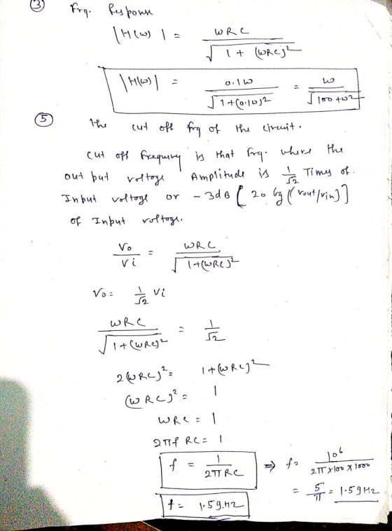
For the circuit shown in the figure above: Obtain an expression for H() Vo/Vi in standard form Generate spectral plots for the magnitude and phase of H (w), given that R-100Ω, L-0.1 mH, and C-1 μF De...
 For the circuit shown in the figure above: Obtain an expression for H() Vo/Vi in standard form Generate spectral plots for the magnitude and phase of H (w), given that R-100Ω, L-0.1 mH, and C-1 μF Determine the cutoff frequency we and the slope of the magnitude (in dB) when wwc >1
For the circuit shown in the figure above: Obtain an expression for H() Vo/Vi in standard form Generate spectral plots for the magnitude and phase of H (w),...
For the circuit shown in the figure above: Obtain an expression for H() Vo/Vi in standard form Generate spectral plots for the magnitude and phase of H (w), given that R-100Ω, L-0.1 mH, and C-1 μF Determine the cutoff frequency we and the slope of the magnitude (in dB) when wwc >1
For the circuit shown in the figure above: Obtain an expression for H() Vo/Vi in standard form Generate spectral plots for the magnitude and phase of H (w),...
PROBLEM III (25 points) The signal v,(t) circuit 2 cos(20rt) cos(10rt) is placed at the input...
 PROBLEM III (25 points) The signal v,(t) circuit 2 cos(20rt) cos(10rt) is placed at the input of a linear and time invariant Ideal #1 low-pass filter with frequency response H(o) al where de 20π. Find the output signal v2(t) using Fourier transform.
 Question 2 (20 points) Consider the circuit below with Vị as the input and v, as the output. Let the component values be R = 33.2, C = 470uF and L = 250mH. R + + yo(t) L - Answer the following questions using the formulas from the lecture slides: 1. What is the type of this filter? (2 points) 2. Write down the expression for the transfer function H(w) of the circuit. (4 points) 3. Write down the expression...
 Question #01 (30 points) Consider the following circuit. Let us define the phasors in terms of the Sine function. 0.25 F 12 H 222 1H = 0.5 F {52 8 sin (2t + 30°) V Zeq + 1. Draw phasor domain circuit. (4 points) 2. Find Zee for the circuit as seen from input voltage source. (6 points) 3. Draw Zeq phasor. (2 points) 4. Find resistance and reactance for Zeq. Is the reactance capacitive or inductive? (3 points) 5....
 21 Vi Z2 Vo Figure 1 1. Ref: Figure 1. Let Z1 L (an inductor), Z2 - R (a resistor). Vi Calculate the magnitude and phase of the transfer function H(w) Figure 1 T 2. Repeat #1 with L = 100 mH, R 1kΩ. a) Plot the frequency response in dB* on a both on a linear scale and then a log scale from ω-1 to 100,000,000 rad/sec with points every decade (1 b) 1,000 etc). 10 100 Plot the...
 1. Consider a continuous-time ideal high-pass filter that removes all frequencies below a given cut-off frequency, and allows all frequencies at or above that cut-off frequency to pass through the system unchanged. That is, the filter will keep frequency w if w] 2we and remove frequency w if ww Let the cutoff frequency we have value 2π. (a) Sketch this filter's frequency response H(ju). (b) Let x(t) 4-3 cos(3m) + 6eMt. Find ak, the Fourier series coefficients of x(t) (c)...
 4. (15 points - PA.3) Consider the RLC circuit shown below, where the input and output x(t) and y(t) are the input voltage vi(t) and capacitor voltage vc(t) respectively, and R = 1 K12, C = 0.1 mF, L = 100 H. i(t) + (i) Determine the frequency response of the system H (jw), as well as its magnitude and phase responses. What type of filter does it correspond to? (ii) Sketch its magnitude and phase response in Matlab. You...
 Consider an electrical system shown in the following circuit diagram RI R2 Show that the transfer function from vi to vo can be expressed as H(s) s a R2 R1R2 and b where a RI R2C RI R2C = 5 x 10⁴ , R2 Compute a and b of the electrical system for R1 C 10-6 F 1020 , and Compute the maximum phase (in degrees) of the electrical system and the correspond ing frequency (in rad/sec) Sketch the frequency...
 The input to the below op-amp circuit is the source voltage vi(t) and the response is the voltage across Rư, vo(t). Design this circuit to satisfy the following two specifications: (a) The phase shift at w = 1000 rad/s is 225 degree. (b) The gain at high frequencies is 10. Ri C = 0.1 uF vilo o Rız volt)
 Consider a causal LTI system implemented as the RL circuit shown below. In this circuit, v(t) is the input voltage. The current i(t) is considered the system output. i(t) R L wwwm v(t) (a) Find the differential equation relating v(t) and i(t). (b) Determine the frequency response of this system (H(jw)). (c) Determine the output it) if v(t) = sin(t), R=10 and L=1. (d) Sketch Bode plot of H (jw) for R=10 and L=1. (e) Determine if the system is...
 For the circuit shown in the figure above: Obtain an expression for H() Vo/Vi in standard form Generate spectral plots for the magnitude and phase of H (w), given that R-100Ω, L-0.1 mH, and C-1 μF Determine the cutoff frequency we and the slope of the magnitude (in dB) when wwc >1
For the circuit shown in the figure above: Obtain an expression for H() Vo/Vi in standard form Generate spectral plots for the magnitude and phase of H (w),...
For the circuit shown in the figure above: Obtain an expression for H() Vo/Vi in standard form Generate spectral plots for the magnitude and phase of H (w), given that R-100Ω, L-0.1 mH, and C-1 μF Determine the cutoff frequency we and the slope of the magnitude (in dB) when wwc >1
For the circuit shown in the figure above: Obtain an expression for H() Vo/Vi in standard form Generate spectral plots for the magnitude and phase of H (w),...
 PROBLEM III (25 points) The signal v,(t) circuit 2 cos(20rt) cos(10rt) is placed at the input of a linear and time invariant Ideal #1 low-pass filter with frequency response H(o) al where de 20π. Find the output signal v2(t) using Fourier transform.
Most questions answered within 3 hours.
-
Write a program to score the paper-rock-scissor game. Each of
two users types in either P,R...
asked 17 minutes ago -
Calculate the equillibrium constent K for a redox reaction that
has E°cell = -.98 V at...
asked 29 minutes ago -
A concave spherical mirror has a radius of curvature of
magnitude 19.6 cm.
(a) Find the...
asked 31 minutes ago -
3. draw a diagram of the magnetic field:
a. around a long straight wire with a...
asked 30 minutes ago -
If you titrated 30.0 mL of 0.1 M HCl with 0.1 M NaOH, indicate
the approximate...
asked 38 minutes ago -
NADH passes electrons into the electron transport chain. List
the carriers that would receive the electrons,...
asked 46 minutes ago -
A cylindrical cable with a resistivity of 1.6x10⁻⁸ Ω·m and cross
sectional area of 3x10⁻⁵ m^2...
asked 46 minutes ago -
True or False.
A consumer with convex preferences who is indifferent between
the bundles (5,2) and...
asked 50 minutes ago -
A diamond's index of refraction for red light, 656 nm, is 2.410,
while that for blue...
asked 1 hour ago -
Compare HPLC, SPE, and GC. Identify the differences, the
advantages, and the weaknesses of each method.
asked 1 hour ago -
Characteristic x-rays emitted by potassium have a wavelength of
0.374 nm. What is the energy of...
asked 1 hour ago -
there is a function to create two random numbers between 1 and
25 and a function...
asked 1 hour ago