
Homework Answers
Add Answer to:
Problem 4: /25 For the circuit shown below, use frequency-domain circuit analysis techniques to determine (a)...
Problem 2: /25 For the circuit shown below, use frequency-domain circuit analysis techniques to determine (a)...
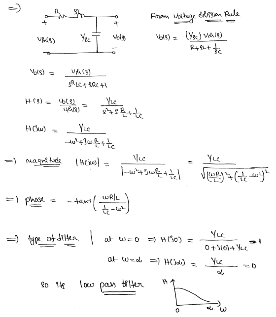
 Problem 2: /25 For the circuit shown below, use frequency-domain circuit analysis techniques to determine (a) the voltage transfer function H(o) of the circuit; (b) the magnitude response H(o) of the circuit; and (c) the phase response (0) of the circuit. (d) Based on the results of parts (a) - (c), identify the type of filter circuit shown. L 10000 + + R Vout(t)
Problem 1: /25 For the circuit shown below, use frequency-domain circuit analysis techniques to determine (a)...
 Problem 1: /25 For the circuit shown below, use frequency-domain circuit analysis techniques to determine (a) the voltage transfer function Ho) of the circuit; (b) the magnitude response H(o) of the circuit; and (c) the phase response (0) of the circuit. (d) Based on the results of parts (a) - (c), identify the type of filter circuit shown. R + Vin(t) llll L Vout(t)
Problem 3: /25 For the circuit shown below, use frequency-domain circuit analysis techniques to determine (a)...
 Problem 3: /25 For the circuit shown below, use frequency-domain circuit analysis techniques to determine (a) the voltage transfer function Ho) of the circuit; (b) the magnitude response H(@) of the circuit; and (c) the phase response (0) of the circuit. (d) Based on the results of parts (a) - (c), identify the type of filter circuit shown. с R + + Vin(t) 0000 L Vout(t)
the circuit shown, 1. Find the transfer function H(jw) 2. If R R2 12 and L1mH, plot the frequency response (both the ga...
 the circuit shown, 1. Find the transfer function H(jw) 2. If R R2 12 and L1mH, plot the frequency response (both the gain and the phase shift) of the circuit; 3. Identify the type of filter the circuit is, and state the break (cut off) frequency. R1 v(t)Vcos(ut) L1 R2 Figure 1
the circuit shown, 1. Find the transfer function H(jw) 2. If R R2 12 and L1mH, plot the frequency response (both the gain and the phase shift) of...
the circuit shown, 1. Find the transfer function H(jw) 2. If R R2 12 and L1mH, plot the frequency response (both the gain and the phase shift) of the circuit; 3. Identify the type of filter the circuit is, and state the break (cut off) frequency. R1 v(t)Vcos(ut) L1 R2 Figure 1
the circuit shown, 1. Find the transfer function H(jw) 2. If R R2 12 and L1mH, plot the frequency response (both the gain and the phase shift) of...
5) Consider the following second-order bandpass filter. As input voltage, apply V(t) 100Ω, C-4.7 μF. and L-10mH. sin(wt).R in Vout Fig 9: Second-order band-pass filter a) Determine the frequenc...
 5) Consider the following second-order bandpass filter. As input voltage, apply V(t) 100Ω, C-4.7 μF. and L-10mH. sin(wt).R in Vout Fig 9: Second-order band-pass filter a) Determine the frequency response function H(ju) Ve-ju) / Vm(ju) and sketch the magnitude and phase characteristics versus w by calaulation. Calculate the theoretical cutoff frequency of the filter Using PSpice AC analysis, plot magnitude lHju)l and phase ф characteristics of the filter, between 1 Hz-100 KHz b) c)
5) Consider the following second-order bandpass...
5) Consider the following second-order bandpass filter. As input voltage, apply V(t) 100Ω, C-4.7 μF. and L-10mH. sin(wt).R in Vout Fig 9: Second-order band-pass filter a) Determine the frequency response function H(ju) Ve-ju) / Vm(ju) and sketch the magnitude and phase characteristics versus w by calaulation. Calculate the theoretical cutoff frequency of the filter Using PSpice AC analysis, plot magnitude lHju)l and phase ф characteristics of the filter, between 1 Hz-100 KHz b) c)
5) Consider the following second-order bandpass...
Question 8: 1. Redraw the circuit shown below with the s domain equivalent models, where V1(t)...
 Question 8: 1. Redraw the circuit shown below with the s domain equivalent models, where V1(t) is a step function from 0 to 1V at t-0 2. Find transfer function in the s domain H( 3. Write the s-domain equation for Vout(s) if V1(s) is a 1V step function. 4. Write the equation of r of the circuit in terms of R's and C 5. Write the equation for the step response in the time domain. 6. You can either...
4. (15 points - PA.3) Consider the RLC circuit shown below, where the input and output...
 4. (15 points - PA.3) Consider the RLC circuit shown below, where the input and output x(t) and y(t) are the input voltage vi(t) and capacitor voltage vc(t) respectively, and R = 1 K12, C = 0.1 mF, L = 100 H. i(t) + (i) Determine the frequency response of the system H (jw), as well as its magnitude and phase responses. What type of filter does it correspond to? (ii) Sketch its magnitude and phase response in Matlab. You...
1. The circuit below, which uses one inductor and two identical resistors, (30 pts] can be...
 1. The circuit below, which uses one inductor and two identical resistors, (30 pts] can be described as a filter. Using this circuit: a. Determine the transfer function, H(@) = Vout/Vin. b. Determine the magnitude and phase (in terms of R, L, and o) of the transfer function from part a. Now, assume R = 5022 and L = 2mH c. What is the value of the magnitude as 0 0 d. The value of the magnitude as → e....
In the series RC circuit below, with R -6.1 k ohms& C 72.5 nF, at what angular frequency [rad/s] ...
 In the series RC circuit below, with R -6.1 k ohms& C 72.5 nF, at what angular frequency [rad/s] does the capacitor AC voltage reduce to its DC value (accurate to 1%)? C output Answer: In the series RC circuit below, with R-1.2 k ohms & C 92.8 nF, calculate the magnitude of the voltage 'gain' of the circuit (Vout/ Vsl), for a driving frequency of 0.1 kHz, to 1% accuracy. Coutput Answer For a series RLC circuit as shown...
Please answer all parts thank you 6. [15 POINTS] Consider a passive low-pass filter as shown...
 Please answer all parts thank
you
6. [15 POINTS] Consider a passive low-pass filter as shown below. 1k2 + - m - + Vin(t) 1 mF Vout(t) a) Derive a transfer function for the above circuit. b) Derive a time-domain expression for the unit impulse response of the circuit. Also, plot the impulse response as a function of time. c) Derive a time-domain expression for the unit step response of the circuit. Also, plot the step response as a function...
Please answer all parts thank
you
6. [15 POINTS] Consider a passive low-pass filter as shown below. 1k2 + - m - + Vin(t) 1 mF Vout(t) a) Derive a transfer function for the above circuit. b) Derive a time-domain expression for the unit impulse response of the circuit. Also, plot the impulse response as a function of time. c) Derive a time-domain expression for the unit step response of the circuit. Also, plot the step response as a function...
 Problem 2: /25 For the circuit shown below, use frequency-domain circuit analysis techniques to determine (a) the voltage transfer function H(o) of the circuit; (b) the magnitude response H(o) of the circuit; and (c) the phase response (0) of the circuit. (d) Based on the results of parts (a) - (c), identify the type of filter circuit shown. L 10000 + + R Vout(t)
 Problem 1: /25 For the circuit shown below, use frequency-domain circuit analysis techniques to determine (a) the voltage transfer function Ho) of the circuit; (b) the magnitude response H(o) of the circuit; and (c) the phase response (0) of the circuit. (d) Based on the results of parts (a) - (c), identify the type of filter circuit shown. R + Vin(t) llll L Vout(t)
 Problem 3: /25 For the circuit shown below, use frequency-domain circuit analysis techniques to determine (a) the voltage transfer function Ho) of the circuit; (b) the magnitude response H(@) of the circuit; and (c) the phase response (0) of the circuit. (d) Based on the results of parts (a) - (c), identify the type of filter circuit shown. с R + + Vin(t) 0000 L Vout(t)
 the circuit shown, 1. Find the transfer function H(jw) 2. If R R2 12 and L1mH, plot the frequency response (both the gain and the phase shift) of the circuit; 3. Identify the type of filter the circuit is, and state the break (cut off) frequency. R1 v(t)Vcos(ut) L1 R2 Figure 1
the circuit shown, 1. Find the transfer function H(jw) 2. If R R2 12 and L1mH, plot the frequency response (both the gain and the phase shift) of...
the circuit shown, 1. Find the transfer function H(jw) 2. If R R2 12 and L1mH, plot the frequency response (both the gain and the phase shift) of the circuit; 3. Identify the type of filter the circuit is, and state the break (cut off) frequency. R1 v(t)Vcos(ut) L1 R2 Figure 1
the circuit shown, 1. Find the transfer function H(jw) 2. If R R2 12 and L1mH, plot the frequency response (both the gain and the phase shift) of...
 5) Consider the following second-order bandpass filter. As input voltage, apply V(t) 100Ω, C-4.7 μF. and L-10mH. sin(wt).R in Vout Fig 9: Second-order band-pass filter a) Determine the frequency response function H(ju) Ve-ju) / Vm(ju) and sketch the magnitude and phase characteristics versus w by calaulation. Calculate the theoretical cutoff frequency of the filter Using PSpice AC analysis, plot magnitude lHju)l and phase ф characteristics of the filter, between 1 Hz-100 KHz b) c)
5) Consider the following second-order bandpass...
5) Consider the following second-order bandpass filter. As input voltage, apply V(t) 100Ω, C-4.7 μF. and L-10mH. sin(wt).R in Vout Fig 9: Second-order band-pass filter a) Determine the frequency response function H(ju) Ve-ju) / Vm(ju) and sketch the magnitude and phase characteristics versus w by calaulation. Calculate the theoretical cutoff frequency of the filter Using PSpice AC analysis, plot magnitude lHju)l and phase ф characteristics of the filter, between 1 Hz-100 KHz b) c)
5) Consider the following second-order bandpass...
 Question 8: 1. Redraw the circuit shown below with the s domain equivalent models, where V1(t) is a step function from 0 to 1V at t-0 2. Find transfer function in the s domain H( 3. Write the s-domain equation for Vout(s) if V1(s) is a 1V step function. 4. Write the equation of r of the circuit in terms of R's and C 5. Write the equation for the step response in the time domain. 6. You can either...
 4. (15 points - PA.3) Consider the RLC circuit shown below, where the input and output x(t) and y(t) are the input voltage vi(t) and capacitor voltage vc(t) respectively, and R = 1 K12, C = 0.1 mF, L = 100 H. i(t) + (i) Determine the frequency response of the system H (jw), as well as its magnitude and phase responses. What type of filter does it correspond to? (ii) Sketch its magnitude and phase response in Matlab. You...
 1. The circuit below, which uses one inductor and two identical resistors, (30 pts] can be described as a filter. Using this circuit: a. Determine the transfer function, H(@) = Vout/Vin. b. Determine the magnitude and phase (in terms of R, L, and o) of the transfer function from part a. Now, assume R = 5022 and L = 2mH c. What is the value of the magnitude as 0 0 d. The value of the magnitude as → e....
 In the series RC circuit below, with R -6.1 k ohms& C 72.5 nF, at what angular frequency [rad/s] does the capacitor AC voltage reduce to its DC value (accurate to 1%)? C output Answer: In the series RC circuit below, with R-1.2 k ohms & C 92.8 nF, calculate the magnitude of the voltage 'gain' of the circuit (Vout/ Vsl), for a driving frequency of 0.1 kHz, to 1% accuracy. Coutput Answer For a series RLC circuit as shown...
 Please answer all parts thank
you
6. [15 POINTS] Consider a passive low-pass filter as shown below. 1k2 + - m - + Vin(t) 1 mF Vout(t) a) Derive a transfer function for the above circuit. b) Derive a time-domain expression for the unit impulse response of the circuit. Also, plot the impulse response as a function of time. c) Derive a time-domain expression for the unit step response of the circuit. Also, plot the step response as a function...
Please answer all parts thank
you
6. [15 POINTS] Consider a passive low-pass filter as shown below. 1k2 + - m - + Vin(t) 1 mF Vout(t) a) Derive a transfer function for the above circuit. b) Derive a time-domain expression for the unit impulse response of the circuit. Also, plot the impulse response as a function of time. c) Derive a time-domain expression for the unit step response of the circuit. Also, plot the step response as a function...
Most questions answered within 3 hours.
-
. A 100.0 mL sample of 0.18 M HClO4 is titrated with 0.27 M
LiOH. Determine...
asked 10 minutes ago -
A regression equation that describes the relationship between
the amount of the bill ($) at a...
asked 1 hour ago -
exercise on VSEPR and molecular structrue.
octahedral
SeCl62-
TeCl62-
ClF62-
distorted
SeF62–
IF6–
asked 1 hour ago -
284 mL of a 0.52 M potassium hydroxide solution is added to 467
mL of a...
asked 1 hour ago -
Little’s Law: Val d’Costa is a world famous ski village in the
French Alps. Because of...
asked 2 hours ago -
Find the absolute error D for the calculation if A + B/C=D A=
9.4 +/- 0.4...
asked 2 hours ago -
New Air Heating and Cooling, manufactures furnaces and central
air units. The company pride itself on...
asked 2 hours ago -
A coach uses a new technique to train gymnasts. Seven
gymnasts were randomly selected and their...
asked 4 hours ago -
While rotating the tires on your car you notice a rock [mass =
0.1 Kg] stuck...
asked 6 hours ago -
Using MARS simulator, write MIPS programs according to
the following scenarios: Receive a positive integer number...
asked 8 hours ago -
An object in front of a concave mirror has a real image that is
11.5 cm...
asked 8 hours ago -
Consider the reaction, C3 H8 + O2 --> CO2 + H2O. How many
moles of O2...
asked 10 hours ago