
Homework Answers
Add Answer to:
Problem 3: /25 For the circuit shown below, use frequency-domain circuit analysis techniques to determine (a)...
Problem 1: /25 For the circuit shown below, use frequency-domain circuit analysis techniques to determine (a)...
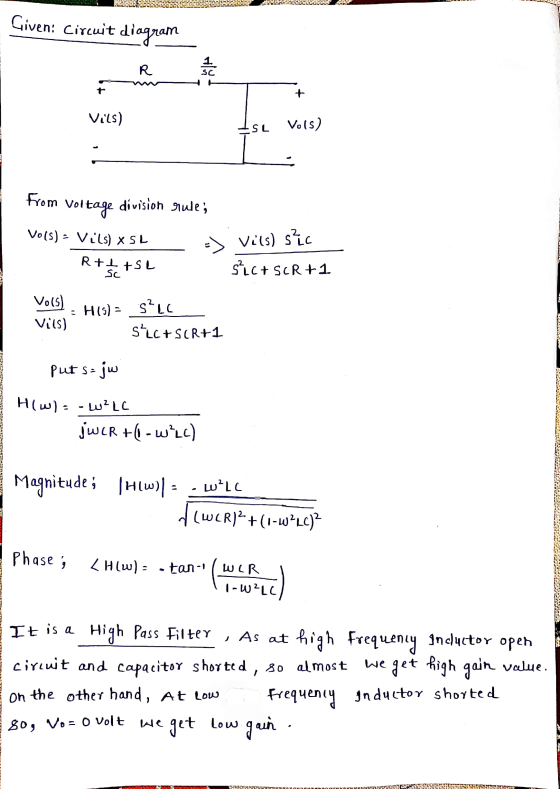
 Problem 1: /25 For the circuit shown below, use frequency-domain circuit analysis techniques to determine (a) the voltage transfer function Ho) of the circuit; (b) the magnitude response H(o) of the circuit; and (c) the phase response (0) of the circuit. (d) Based on the results of parts (a) - (c), identify the type of filter circuit shown. R + Vin(t) llll L Vout(t)
Problem 4: /25 For the circuit shown below, use frequency-domain circuit analysis techniques to determine (a)...
 Problem 4: /25 For the circuit shown below, use frequency-domain circuit analysis techniques to determine (a) the voltage transfer function Hw) of the circuit; (b) the magnitude response H(o) of the circuit; and (c) the phase response (0) of the circuit. (d) Based on the results of parts (a) - (c), identify the type of filter circuit shown. R L 10000 + + Vout(t)
Problem 2: /25 For the circuit shown below, use frequency-domain circuit analysis techniques to determine (a)...
 Problem 2: /25 For the circuit shown below, use frequency-domain circuit analysis techniques to determine (a) the voltage transfer function H(o) of the circuit; (b) the magnitude response H(o) of the circuit; and (c) the phase response (0) of the circuit. (d) Based on the results of parts (a) - (c), identify the type of filter circuit shown. L 10000 + + R Vout(t)
Please answer all parts thank you 6. [15 POINTS] Consider a passive low-pass filter as shown...
 Please answer all parts thank
you
6. [15 POINTS] Consider a passive low-pass filter as shown below. 1k2 + - m - + Vin(t) 1 mF Vout(t) a) Derive a transfer function for the above circuit. b) Derive a time-domain expression for the unit impulse response of the circuit. Also, plot the impulse response as a function of time. c) Derive a time-domain expression for the unit step response of the circuit. Also, plot the step response as a function...
Please answer all parts thank
you
6. [15 POINTS] Consider a passive low-pass filter as shown below. 1k2 + - m - + Vin(t) 1 mF Vout(t) a) Derive a transfer function for the above circuit. b) Derive a time-domain expression for the unit impulse response of the circuit. Also, plot the impulse response as a function of time. c) Derive a time-domain expression for the unit step response of the circuit. Also, plot the step response as a function...
Purpose: Use Laplace transforms to find the time domain response of a RLC band-pass filter to...
 Purpose: Use Laplace transforms to find the time domain response of a RLC band-pass filter to step and impulse inputs Vout Vin L=27 mH For the RLC circuit above Find the s-domain transfer function: Find the impulse response h(t) H(s) = Vout(s)/Vin(s) · These operations must be performed by hand using Laplace transforms, do not use MATLAB or a circuit simulator. We will verify your hand calculations in lab. Hints: To find the transfer function, find the equivalent impedance of...
the circuit shown, 1. Find the transfer function H(jw) 2. If R R2 12 and L1mH, plot the frequency response (both the ga...
 the circuit shown, 1. Find the transfer function H(jw) 2. If R R2 12 and L1mH, plot the frequency response (both the gain and the phase shift) of the circuit; 3. Identify the type of filter the circuit is, and state the break (cut off) frequency. R1 v(t)Vcos(ut) L1 R2 Figure 1
the circuit shown, 1. Find the transfer function H(jw) 2. If R R2 12 and L1mH, plot the frequency response (both the gain and the phase shift) of...
the circuit shown, 1. Find the transfer function H(jw) 2. If R R2 12 and L1mH, plot the frequency response (both the gain and the phase shift) of the circuit; 3. Identify the type of filter the circuit is, and state the break (cut off) frequency. R1 v(t)Vcos(ut) L1 R2 Figure 1
the circuit shown, 1. Find the transfer function H(jw) 2. If R R2 12 and L1mH, plot the frequency response (both the gain and the phase shift) of...
Question 8: 1. Redraw the circuit shown below with the s domain equivalent models, where V1(t)...
 Question 8: 1. Redraw the circuit shown below with the s domain equivalent models, where V1(t) is a step function from 0 to 1V at t-0 2. Find transfer function in the s domain H( 3. Write the s-domain equation for Vout(s) if V1(s) is a 1V step function. 4. Write the equation of r of the circuit in terms of R's and C 5. Write the equation for the step response in the time domain. 6. You can either...
the voltage transfer function Avi) Vo(s)/Vin(s) (s-plane representation) for your selected circuit. What is the frequency...
 the voltage transfer function Avi) Vo(s)/Vin(s) (s-plane representation) for your selected circuit. What is the frequency response for this circuit (both magnitude and phase)? What is the corner frequency in Hz and rad/sec? What kind of filter is this? (2+2+1+1) points 1 Vi ?.
1. The circuit below, which uses one inductor and two identical resistors, (30 pts] can be...
 1. The circuit below, which uses one inductor and two identical resistors, (30 pts] can be described as a filter. Using this circuit: a. Determine the transfer function, H(@) = Vout/Vin. b. Determine the magnitude and phase (in terms of R, L, and o) of the transfer function from part a. Now, assume R = 5022 and L = 2mH c. What is the value of the magnitude as 0 0 d. The value of the magnitude as → e....
 Problem 1: /25 For the circuit shown below, use frequency-domain circuit analysis techniques to determine (a) the voltage transfer function Ho) of the circuit; (b) the magnitude response H(o) of the circuit; and (c) the phase response (0) of the circuit. (d) Based on the results of parts (a) - (c), identify the type of filter circuit shown. R + Vin(t) llll L Vout(t)
 Problem 4: /25 For the circuit shown below, use frequency-domain circuit analysis techniques to determine (a) the voltage transfer function Hw) of the circuit; (b) the magnitude response H(o) of the circuit; and (c) the phase response (0) of the circuit. (d) Based on the results of parts (a) - (c), identify the type of filter circuit shown. R L 10000 + + Vout(t)
 Problem 2: /25 For the circuit shown below, use frequency-domain circuit analysis techniques to determine (a) the voltage transfer function H(o) of the circuit; (b) the magnitude response H(o) of the circuit; and (c) the phase response (0) of the circuit. (d) Based on the results of parts (a) - (c), identify the type of filter circuit shown. L 10000 + + R Vout(t)
 Please answer all parts thank
you
6. [15 POINTS] Consider a passive low-pass filter as shown below. 1k2 + - m - + Vin(t) 1 mF Vout(t) a) Derive a transfer function for the above circuit. b) Derive a time-domain expression for the unit impulse response of the circuit. Also, plot the impulse response as a function of time. c) Derive a time-domain expression for the unit step response of the circuit. Also, plot the step response as a function...
Please answer all parts thank
you
6. [15 POINTS] Consider a passive low-pass filter as shown below. 1k2 + - m - + Vin(t) 1 mF Vout(t) a) Derive a transfer function for the above circuit. b) Derive a time-domain expression for the unit impulse response of the circuit. Also, plot the impulse response as a function of time. c) Derive a time-domain expression for the unit step response of the circuit. Also, plot the step response as a function...
 Purpose: Use Laplace transforms to find the time domain response of a RLC band-pass filter to step and impulse inputs Vout Vin L=27 mH For the RLC circuit above Find the s-domain transfer function: Find the impulse response h(t) H(s) = Vout(s)/Vin(s) · These operations must be performed by hand using Laplace transforms, do not use MATLAB or a circuit simulator. We will verify your hand calculations in lab. Hints: To find the transfer function, find the equivalent impedance of...
 the circuit shown, 1. Find the transfer function H(jw) 2. If R R2 12 and L1mH, plot the frequency response (both the gain and the phase shift) of the circuit; 3. Identify the type of filter the circuit is, and state the break (cut off) frequency. R1 v(t)Vcos(ut) L1 R2 Figure 1
the circuit shown, 1. Find the transfer function H(jw) 2. If R R2 12 and L1mH, plot the frequency response (both the gain and the phase shift) of...
the circuit shown, 1. Find the transfer function H(jw) 2. If R R2 12 and L1mH, plot the frequency response (both the gain and the phase shift) of the circuit; 3. Identify the type of filter the circuit is, and state the break (cut off) frequency. R1 v(t)Vcos(ut) L1 R2 Figure 1
the circuit shown, 1. Find the transfer function H(jw) 2. If R R2 12 and L1mH, plot the frequency response (both the gain and the phase shift) of...
 Question 8: 1. Redraw the circuit shown below with the s domain equivalent models, where V1(t) is a step function from 0 to 1V at t-0 2. Find transfer function in the s domain H( 3. Write the s-domain equation for Vout(s) if V1(s) is a 1V step function. 4. Write the equation of r of the circuit in terms of R's and C 5. Write the equation for the step response in the time domain. 6. You can either...
 the voltage transfer function Avi) Vo(s)/Vin(s) (s-plane representation) for your selected circuit. What is the frequency response for this circuit (both magnitude and phase)? What is the corner frequency in Hz and rad/sec? What kind of filter is this? (2+2+1+1) points 1 Vi ?.
 1. The circuit below, which uses one inductor and two identical resistors, (30 pts] can be described as a filter. Using this circuit: a. Determine the transfer function, H(@) = Vout/Vin. b. Determine the magnitude and phase (in terms of R, L, and o) of the transfer function from part a. Now, assume R = 5022 and L = 2mH c. What is the value of the magnitude as 0 0 d. The value of the magnitude as → e....
Most questions answered within 3 hours.
-
A 0.0510 M solution of an organic acid has an
[H+] of 7.50×10⁻⁴M .
What is...
asked 54 seconds from now -
The completed Lewis structure of CO2 contains a total
of 0,1,2,3,4,5,6,7,8 covalent bonds
and 0,1,2,3,4,5,6,7,8 lone pairs.
NOTE:...
asked 2 minutes ago -
what is the profit-maximizing output condition that a
monopolistically competitive firm must satisfy? a) price charged...
asked 3 minutes ago -
Consider the set of ordered pairs shown below. Assuming that the
regression equation is y=3.513+0.429x and...
asked 24 minutes ago -
1. (A) Write two
structural (constitutional)
isomers of C4H8F2?
Please show all of
the
asked 27 minutes ago -
Objective: Practice converting a Boolean logic
expression into it’s truth table and to show the implementation...
asked 24 minutes ago -
1) Name the three holes located in the greater wing of the
sphenoid bone in order...
asked 27 minutes ago -
For the following reaction set-up, which type of hydrocarbon
product would form? 1,4-hexadiene + two Cl2...
asked 30 minutes ago -
Consider the following method that is intended to determine if
the double values d1 and d2...
asked 42 minutes ago -
could someone please post clear drawings of the three structures
in the equilibrium mixture of D-glucose...
asked 49 minutes ago -
Using the Properties of Order show that 5n5 +
4n4 + 6n3 + 2n2+ n +...
asked 52 minutes ago -
What is experiential learning and how is it helpful for teaching
leadership, and interpreting group dynamics?...
asked 52 minutes ago