
Homework Answers
Add Answer to:
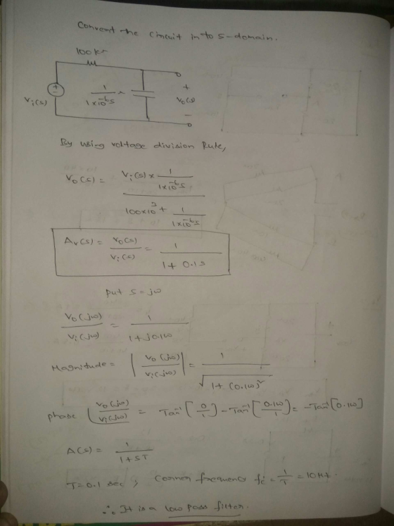
the voltage transfer function Avi) Vo(s)/Vin(s) (s-plane representation) for your selected circuit. What is the frequency...
Consider an electrical system shown in the following circuit diagram RI R2 Show that the transfer...
 Consider an electrical system shown in the following circuit diagram RI R2 Show that the transfer function from vi to vo can be expressed as H(s) s a R2 R1R2 and b where a RI R2C RI R2C = 5 x 10⁴ , R2 Compute a and b of the electrical system for R1 C 10-6 F 1020 , and Compute the maximum phase (in degrees) of the electrical system and the correspond ing frequency (in rad/sec) Sketch the frequency...
Problem 2 An RC circuit ( with an active component) has the following transfer function (where...
 Problem 2 An RC circuit ( with an active component) has the following transfer function (where R and Care positive) H(s) - Vout(8) _R|| R/10k12 Vin(8) 10KN 1 + $RC Where s = jw Find the value of the resistor and the value of the capacitor so that: for w = 0 rad/s, H(jw)lde = +12dB at f = 1kHz, |H(jw)lab = +9dB Problem 3 The transfer function of a circuit is given by H(S) = Vout(s) Vin(s) Where s...
This filter is an active bandpass filter Compute the transfer function for the circuit of in term...
 This filter is an active bandpass filter
Compute the transfer function for the circuit of in
terms of the circuit constants R1 R2 R3 C1 and C2. Then, replace
the complex variable with omega, and the circuit constants with
their numerical values and plot the magnitude versus radian
frequency .
What kind of filter is this? Find the transfer function of the circuit and Use MATLAB to plot IVout/Vin over frequency to verify your answer. 0.01 μF 106.1 kΩ 0...
This filter is an active bandpass filter
Compute the transfer function for the circuit of in
terms of the circuit constants R1 R2 R3 C1 and C2. Then, replace
the complex variable with omega, and the circuit constants with
their numerical values and plot the magnitude versus radian
frequency .
What kind of filter is this? Find the transfer function of the circuit and Use MATLAB to plot IVout/Vin over frequency to verify your answer. 0.01 μF 106.1 kΩ 0...
A system is described by the following transfer function: A) What is the frequency response, H(f)?...
 A system is described by the following transfer function:
A) What is the frequency response, H(f)?
B) What is the magnitude and phase (in degrees) of the frequency
response at a frequency of w=3 rads/sec, corresponding to
hz?
$2 + 16 H(s) = - 11s(s+2)(2+1) We were unable to transcribe this image
A system is described by the following transfer function:
A) What is the frequency response, H(f)?
B) What is the magnitude and phase (in degrees) of the frequency
response at a frequency of w=3 rads/sec, corresponding to
hz?
$2 + 16 H(s) = - 11s(s+2)(2+1) We were unable to transcribe this image
Find the transfer function H(jω) for the circuit above as a function of jω. (Leave R...
 Find the transfer function H(jω) for the
circuit above as a function of jω. (Leave R and L as variables).
Assume V R to be the output and V S to be the input.
С L RVR(t) vs (t) A. Find the transfer function H(jo) for the circuit above as a function of jaw. (Leave R and L as variables). Assume V to be the output and V to be the input. S R B. Find the Magnitude and Phase...
Find the transfer function H(jω) for the
circuit above as a function of jω. (Leave R and L as variables).
Assume V R to be the output and V S to be the input.
С L RVR(t) vs (t) A. Find the transfer function H(jo) for the circuit above as a function of jaw. (Leave R and L as variables). Assume V to be the output and V to be the input. S R B. Find the Magnitude and Phase...
21 Vi Z2 Vo Figure 1 1. Ref: Figure 1. Let Z1 L (an inductor), Z2 - R (a resistor). Vi Calculate the magnitude and phase of the transfer function H(w) Figure 1 T 2. Repeat #1 with L = 100 mH, R 1kΩ....
 21 Vi Z2 Vo Figure 1 1. Ref: Figure 1. Let Z1 L (an inductor), Z2 - R (a resistor). Vi Calculate the magnitude and phase of the transfer function H(w) Figure 1 T 2. Repeat #1 with L = 100 mH, R 1kΩ. a) Plot the frequency response in dB* on a both on a linear scale and then a log scale from ω-1 to 100,000,000 rad/sec with points every decade (1 b) 1,000 etc). 10 100 Plot the...
Problem 1: /25 For the circuit shown below, use frequency-domain circuit analysis techniques to determine (a)...
 Problem 1: /25 For the circuit shown below, use frequency-domain circuit analysis techniques to determine (a) the voltage transfer function Ho) of the circuit; (b) the magnitude response H(o) of the circuit; and (c) the phase response (0) of the circuit. (d) Based on the results of parts (a) - (c), identify the type of filter circuit shown. R + Vin(t) llll L Vout(t)
Q1. For the filter circuit shown below, (5 marks) Vo(s) a) Find the transfer function, G(s)...
 Q1. For the filter circuit shown below, (5 marks) Vo(s) a) Find the transfer function, G(s) and the type of the filter. (4 marks) Vi(s)' b) Find the initial and final values of vo(t) if vi(t) = 2u(t). (1 marks) 10 k12 w 6 тн 0000 v;(1) 5 k92 2 mF
Problem 3: /25 For the circuit shown below, use frequency-domain circuit analysis techniques to determine (a)...
 Problem 3: /25 For the circuit shown below, use frequency-domain circuit analysis techniques to determine (a) the voltage transfer function Ho) of the circuit; (b) the magnitude response H(@) of the circuit; and (c) the phase response (0) of the circuit. (d) Based on the results of parts (a) - (c), identify the type of filter circuit shown. с R + + Vin(t) 0000 L Vout(t)
6) Use the RC filter to the right. a) (10pts) Find the voltage gain (Vo/Vin) of...
 6) Use the RC filter to the right. a) (10pts) Find the voltage gain (Vo/Vin) of the circuit for very low frequencies, 12kΩ 10nF V va b) (10pts) Find the voltage gain of the previous answer in dB. c) (40pts) Use the provided semi-log grid to create an idealized Bode magnitude plot of the circuit's voltage gain. Be sure to label the cutoff frequency (Hz) and to properly represent any nonzero slopes. 6d) (20pts) Find the circuit's actual voltage gain...
 Consider an electrical system shown in the following circuit diagram RI R2 Show that the transfer function from vi to vo can be expressed as H(s) s a R2 R1R2 and b where a RI R2C RI R2C = 5 x 10⁴ , R2 Compute a and b of the electrical system for R1 C 10-6 F 1020 , and Compute the maximum phase (in degrees) of the electrical system and the correspond ing frequency (in rad/sec) Sketch the frequency...
 Problem 2 An RC circuit ( with an active component) has the following transfer function (where R and Care positive) H(s) - Vout(8) _R|| R/10k12 Vin(8) 10KN 1 + $RC Where s = jw Find the value of the resistor and the value of the capacitor so that: for w = 0 rad/s, H(jw)lde = +12dB at f = 1kHz, |H(jw)lab = +9dB Problem 3 The transfer function of a circuit is given by H(S) = Vout(s) Vin(s) Where s...
 This filter is an active bandpass filter
Compute the transfer function for the circuit of in
terms of the circuit constants R1 R2 R3 C1 and C2. Then, replace
the complex variable with omega, and the circuit constants with
their numerical values and plot the magnitude versus radian
frequency .
What kind of filter is this? Find the transfer function of the circuit and Use MATLAB to plot IVout/Vin over frequency to verify your answer. 0.01 μF 106.1 kΩ 0...
This filter is an active bandpass filter
Compute the transfer function for the circuit of in
terms of the circuit constants R1 R2 R3 C1 and C2. Then, replace
the complex variable with omega, and the circuit constants with
their numerical values and plot the magnitude versus radian
frequency .
What kind of filter is this? Find the transfer function of the circuit and Use MATLAB to plot IVout/Vin over frequency to verify your answer. 0.01 μF 106.1 kΩ 0...
 A system is described by the following transfer function:
A) What is the frequency response, H(f)?
B) What is the magnitude and phase (in degrees) of the frequency
response at a frequency of w=3 rads/sec, corresponding to
hz?
$2 + 16 H(s) = - 11s(s+2)(2+1) We were unable to transcribe this image
A system is described by the following transfer function:
A) What is the frequency response, H(f)?
B) What is the magnitude and phase (in degrees) of the frequency
response at a frequency of w=3 rads/sec, corresponding to
hz?
$2 + 16 H(s) = - 11s(s+2)(2+1) We were unable to transcribe this image
 Find the transfer function H(jω) for the
circuit above as a function of jω. (Leave R and L as variables).
Assume V R to be the output and V S to be the input.
С L RVR(t) vs (t) A. Find the transfer function H(jo) for the circuit above as a function of jaw. (Leave R and L as variables). Assume V to be the output and V to be the input. S R B. Find the Magnitude and Phase...
Find the transfer function H(jω) for the
circuit above as a function of jω. (Leave R and L as variables).
Assume V R to be the output and V S to be the input.
С L RVR(t) vs (t) A. Find the transfer function H(jo) for the circuit above as a function of jaw. (Leave R and L as variables). Assume V to be the output and V to be the input. S R B. Find the Magnitude and Phase...
 21 Vi Z2 Vo Figure 1 1. Ref: Figure 1. Let Z1 L (an inductor), Z2 - R (a resistor). Vi Calculate the magnitude and phase of the transfer function H(w) Figure 1 T 2. Repeat #1 with L = 100 mH, R 1kΩ. a) Plot the frequency response in dB* on a both on a linear scale and then a log scale from ω-1 to 100,000,000 rad/sec with points every decade (1 b) 1,000 etc). 10 100 Plot the...
 Problem 1: /25 For the circuit shown below, use frequency-domain circuit analysis techniques to determine (a) the voltage transfer function Ho) of the circuit; (b) the magnitude response H(o) of the circuit; and (c) the phase response (0) of the circuit. (d) Based on the results of parts (a) - (c), identify the type of filter circuit shown. R + Vin(t) llll L Vout(t)
 Q1. For the filter circuit shown below, (5 marks) Vo(s) a) Find the transfer function, G(s) and the type of the filter. (4 marks) Vi(s)' b) Find the initial and final values of vo(t) if vi(t) = 2u(t). (1 marks) 10 k12 w 6 тн 0000 v;(1) 5 k92 2 mF
 Problem 3: /25 For the circuit shown below, use frequency-domain circuit analysis techniques to determine (a) the voltage transfer function Ho) of the circuit; (b) the magnitude response H(@) of the circuit; and (c) the phase response (0) of the circuit. (d) Based on the results of parts (a) - (c), identify the type of filter circuit shown. с R + + Vin(t) 0000 L Vout(t)
 6) Use the RC filter to the right. a) (10pts) Find the voltage gain (Vo/Vin) of the circuit for very low frequencies, 12kΩ 10nF V va b) (10pts) Find the voltage gain of the previous answer in dB. c) (40pts) Use the provided semi-log grid to create an idealized Bode magnitude plot of the circuit's voltage gain. Be sure to label the cutoff frequency (Hz) and to properly represent any nonzero slopes. 6d) (20pts) Find the circuit's actual voltage gain...
Most questions answered within 3 hours.
-
•Let’s say someone claims the average population size is
600 feet squared and the housing authority...
asked 3 minutes ago -
Cynaide is a deadly poison that blocks the last step in the
electron transport chain of...
asked 7 minutes ago -
Your friend tells you that there is a vending machine on campus
that dispenses M&M packs...
asked 23 minutes ago -
What advantages are there to using piperidine rather than
hydroxide as a base?
asked 21 minutes ago -
7. The life of a Freeze Breeze electric fan is normally
distributed with a mean 4...
asked 24 minutes ago -
1. A 751 mL NaCl solution is diluted to a volume of 1.06 L and a...
asked 29 minutes ago -
8
A $20,000 face value STRIPS is currently quoted at 38.642 and
has 8 years to...
asked 29 minutes ago -
The current exchange rate between the Japanese yen and
the US dollar is 120 yen per...
asked 31 minutes ago -
Marla’s Massages and More bought a special massage table two
years ago for $9,300. At the...
asked 38 minutes ago -
Suppose you require a peak output voltage of 15.0 V and have
available an AC source...
asked 39 minutes ago -
We
conduct A study to estimate the mean age of the population of women
at the...
asked 50 minutes ago -
.13 : Assume that we make an enhancement to a computer that
improves some mode of...
asked 52 minutes ago