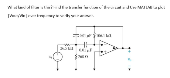
This filter is an active bandpass filter
Compute the transfer function for the circuit of in
terms of the circuit constants R1 R2 R3 C1 and C2. Then, replace
the complex variable with omega, and the circuit constants with
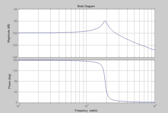
their numerical values and plot the magnitude versus radian
frequency .
Homework Answers


![1clear all: 2-num [-3773.5851: num-[-3773.585] den= [1 1885.0141 sys tf (num, den) 3.552362*10^8]; 5bode (sys) 6-grid on,;](http://img.homeworklib.com/images/97d4dd3f-0a9d-4acf-9db9-0ef30ff1817a.png?x-oss-process=image/resize,w_560)
In case you have any doubts or you did not understand any step please feel free to ask your doubts in the comments section. I would be happy to clarify it.
Add Answer to:
This filter is an active bandpass filter Compute the transfer function for the circuit of in term...
Design an active unity-gain bandpass filter with center frequency 750 Hz and bandwidtg 250 Hz and...
 Design an active unity-gain bandpass filter with
center frequency 750 Hz and bandwidtg 250 Hz and with 0.1 μF
capacitor, R1=6.4kΩ, R2=377Ω, and R3=12.7kΩ.
a)Discuss the circuit response with support of a Bode
magnitude plot.
b) Assume next that a load R_L is connected to the output of the
network at the terminal Vo(s). How does the frequency response of
the loaded configuration change?
c) Consider a broadband bandpass op amp filter with center
frequency 2.4 kHz and bandwidth 800...
Design an active unity-gain bandpass filter with
center frequency 750 Hz and bandwidtg 250 Hz and with 0.1 μF
capacitor, R1=6.4kΩ, R2=377Ω, and R3=12.7kΩ.
a)Discuss the circuit response with support of a Bode
magnitude plot.
b) Assume next that a load R_L is connected to the output of the
network at the terminal Vo(s). How does the frequency response of
the loaded configuration change?
c) Consider a broadband bandpass op amp filter with center
frequency 2.4 kHz and bandwidth 800...
Problem 3. Show that the circuit shown below behaves as a bandpass filter. (Hint-find the transfer...
 Problem 3. Show that the circuit shown below behaves as a bandpass filter. (Hint-find the transfer function for this circuit and show that it has the same form as the transfer function for a bandpass filter. a) Find he center frequency, bandwidth and gain for this bandpass filter. b) Find the cutoff frequencies and the quality for this bandpass filter 10 AF HA 400 SOLF
Hi everyone, I have a question about active filter, including a simulation, Please provide the sc...
 Hi everyone, I have a question about active filter, including a
simulation,
Please provide the screen capture.
Thanks.
5. Active Filter - III Consider the RC op-amp circuit shown in Fig. 5.4. Vin(t) is a sinusoidal signal with Vpp = 1 V, Rı = 10 ㏀ , R, = 20 ㏀ , and C,-C,-0.01 μF. Use Vcc-15V, The capacitors have zero initial energy stored. Ri 741 C1 C2 Volt) Fig. 5.5: Active filter - III (a) Find the transfer function...
Hi everyone, I have a question about active filter, including a
simulation,
Please provide the screen capture.
Thanks.
5. Active Filter - III Consider the RC op-amp circuit shown in Fig. 5.4. Vin(t) is a sinusoidal signal with Vpp = 1 V, Rı = 10 ㏀ , R, = 20 ㏀ , and C,-C,-0.01 μF. Use Vcc-15V, The capacitors have zero initial energy stored. Ri 741 C1 C2 Volt) Fig. 5.5: Active filter - III (a) Find the transfer function...
QUESTION #2 PLEASE 1. Derive the transfer function for the circuit shown below. Plot H(s) versus...
 QUESTION #2 PLEASE
1. Derive the transfer function for the circuit shown below. Plot H(s) versus frequency in Hertz, on a semilog scale. Ri 11.3 k Ri 22.6 k R R = 68.1 kN R3 C C 0.01 uF R2 Vout(s) Vin(s) C2 10 (s+5) H(s) = (s+100)(s5000) , (a) draw the magnitude Bode plot 2. For the transfer function and find the approximate maximum value of (H(jw) in dB, (b) find the value of w where 1 for w>5...
QUESTION #2 PLEASE
1. Derive the transfer function for the circuit shown below. Plot H(s) versus frequency in Hertz, on a semilog scale. Ri 11.3 k Ri 22.6 k R R = 68.1 kN R3 C C 0.01 uF R2 Vout(s) Vin(s) C2 10 (s+5) H(s) = (s+100)(s5000) , (a) draw the magnitude Bode plot 2. For the transfer function and find the approximate maximum value of (H(jw) in dB, (b) find the value of w where 1 for w>5...
Hi everyone, I have an very urgent question with calculating transfer function in MATLAB.(I have a...
 Hi everyone, I have an very urgent question with calculating
transfer function in MATLAB.(I have a test in hours)
Please help me with it.Thanks a lot.
Background:
Question:
Thank
you very much.
Q4. Consider again the bandpass filter with a transfer function of R H(s) 1 R+sL+ sC where Q5. The signal delay through the second order filter of Q4 is given by the rate of change of the phase shift of the filter with respect to excitation frequency. That...
Hi everyone, I have an very urgent question with calculating
transfer function in MATLAB.(I have a test in hours)
Please help me with it.Thanks a lot.
Background:
Question:
Thank
you very much.
Q4. Consider again the bandpass filter with a transfer function of R H(s) 1 R+sL+ sC where Q5. The signal delay through the second order filter of Q4 is given by the rate of change of the phase shift of the filter with respect to excitation frequency. That...
Consider the following transfer function of a bandpass filter: 20 1,500 T(S) = 2 1,500 +...
 Consider the following transfer function of a bandpass filter: 20 1,500 T(S) = 2 1,500 + 1)(30.000 +1) a) Draw the Bode plot (magnitude and phase) of T(s). Label the slopes (dB/decade) b) Name the filter type. c) Determine the resonant frequency o d) Determine the gain in dB at the resonant frequency e) Determine bandwidth B, and the quality factor of the filter. Magnitude (dB) Phase (Deg)
Design a 5-tap FIR bandpass filter
Design a 5-tap FIR bandpass filter with a lower cutoff frequency of1,600 Hz, an upper cutoff frequency of 1,800 Hz, and a sampling rateof 8,000 Hz using a. rectangular window functionb. Hamming window function.Determine the transfer function and difference equation of the designedFIR system, and compute and plot the magnitude frequency responsefor Ω= 0, π/4, π/2, 3π/4, and π radians.PLEASE SHOW STEPS CLEARLY
please need correct answer. I will upvote. Design a second-order digital bandpass Butterworth filter with a...
please need correct answer. I will upvote. Design a second-order digital bandpass Butterworth filter with a lower cutoff frequency of 1.9 kHz, an upper cutoff frequency 2.1 kHz, and a passband ripple of 3dB at a sampling frequency of 8,000 Hz. a. Determine the transfer function and difference equation. b. Use MATLAB to plot the magnitude and phase frequency respon
1. Design a parallel RLC bandpass filter, derive the transfer function H(s). Compute the center frequency, Wo. Calculate the cutoff frequencies Wej and Wc2, the bandwidth ß, and quality factor, Q. Co...
 1. Design a parallel RLC bandpass filter, derive the transfer function H(s). Compute the center frequency, Wo. Calculate the cutoff frequencies Wej and Wc2, the bandwidth ß, and quality factor, Q. Compute values for R and L to yield a bandpass filter with a center frequency of 5kHz and a bandwidth of 200Hz, using a 10nF capacitor. (25 points)
1. Design a parallel RLC bandpass filter, derive the transfer function H(s). Compute the center frequency, Wo. Calculate the cutoff frequencies...
1. Design a parallel RLC bandpass filter, derive the transfer function H(s). Compute the center frequency, Wo. Calculate the cutoff frequencies Wej and Wc2, the bandwidth ß, and quality factor, Q. Compute values for R and L to yield a bandpass filter with a center frequency of 5kHz and a bandwidth of 200Hz, using a 10nF capacitor. (25 points)
1. Design a parallel RLC bandpass filter, derive the transfer function H(s). Compute the center frequency, Wo. Calculate the cutoff frequencies...
For each filter mentioned in the following cases, first simulate the circuit using Multisim. You can get a plot of the transfer function that is called the Bode plot. From the right toolbar, select &...
 For each filter mentioned in the following cases, first simulate the circuit using Multisim. You can get a plot of the transfer function that is called the Bode plot. From the right toolbar, select "Bode Plotter". Change initial (I) and final (F frequencies to 1Hz and 200 KHz, respectively. Use a Voltage AC source as the input signal. You do not need to change any parameter from voltage AC source Connect "Bode Plotter" to input and output of your circuit...
 Design an active unity-gain bandpass filter with
center frequency 750 Hz and bandwidtg 250 Hz and with 0.1 μF
capacitor, R1=6.4kΩ, R2=377Ω, and R3=12.7kΩ.
a)Discuss the circuit response with support of a Bode
magnitude plot.
b) Assume next that a load R_L is connected to the output of the
network at the terminal Vo(s). How does the frequency response of
the loaded configuration change?
c) Consider a broadband bandpass op amp filter with center
frequency 2.4 kHz and bandwidth 800...
Design an active unity-gain bandpass filter with
center frequency 750 Hz and bandwidtg 250 Hz and with 0.1 μF
capacitor, R1=6.4kΩ, R2=377Ω, and R3=12.7kΩ.
a)Discuss the circuit response with support of a Bode
magnitude plot.
b) Assume next that a load R_L is connected to the output of the
network at the terminal Vo(s). How does the frequency response of
the loaded configuration change?
c) Consider a broadband bandpass op amp filter with center
frequency 2.4 kHz and bandwidth 800...
 Problem 3. Show that the circuit shown below behaves as a bandpass filter. (Hint-find the transfer function for this circuit and show that it has the same form as the transfer function for a bandpass filter. a) Find he center frequency, bandwidth and gain for this bandpass filter. b) Find the cutoff frequencies and the quality for this bandpass filter 10 AF HA 400 SOLF
 Hi everyone, I have a question about active filter, including a
simulation,
Please provide the screen capture.
Thanks.
5. Active Filter - III Consider the RC op-amp circuit shown in Fig. 5.4. Vin(t) is a sinusoidal signal with Vpp = 1 V, Rı = 10 ㏀ , R, = 20 ㏀ , and C,-C,-0.01 μF. Use Vcc-15V, The capacitors have zero initial energy stored. Ri 741 C1 C2 Volt) Fig. 5.5: Active filter - III (a) Find the transfer function...
Hi everyone, I have a question about active filter, including a
simulation,
Please provide the screen capture.
Thanks.
5. Active Filter - III Consider the RC op-amp circuit shown in Fig. 5.4. Vin(t) is a sinusoidal signal with Vpp = 1 V, Rı = 10 ㏀ , R, = 20 ㏀ , and C,-C,-0.01 μF. Use Vcc-15V, The capacitors have zero initial energy stored. Ri 741 C1 C2 Volt) Fig. 5.5: Active filter - III (a) Find the transfer function...
 QUESTION #2 PLEASE
1. Derive the transfer function for the circuit shown below. Plot H(s) versus frequency in Hertz, on a semilog scale. Ri 11.3 k Ri 22.6 k R R = 68.1 kN R3 C C 0.01 uF R2 Vout(s) Vin(s) C2 10 (s+5) H(s) = (s+100)(s5000) , (a) draw the magnitude Bode plot 2. For the transfer function and find the approximate maximum value of (H(jw) in dB, (b) find the value of w where 1 for w>5...
QUESTION #2 PLEASE
1. Derive the transfer function for the circuit shown below. Plot H(s) versus frequency in Hertz, on a semilog scale. Ri 11.3 k Ri 22.6 k R R = 68.1 kN R3 C C 0.01 uF R2 Vout(s) Vin(s) C2 10 (s+5) H(s) = (s+100)(s5000) , (a) draw the magnitude Bode plot 2. For the transfer function and find the approximate maximum value of (H(jw) in dB, (b) find the value of w where 1 for w>5...
 Hi everyone, I have an very urgent question with calculating
transfer function in MATLAB.(I have a test in hours)
Please help me with it.Thanks a lot.
Background:
Question:
Thank
you very much.
Q4. Consider again the bandpass filter with a transfer function of R H(s) 1 R+sL+ sC where Q5. The signal delay through the second order filter of Q4 is given by the rate of change of the phase shift of the filter with respect to excitation frequency. That...
Hi everyone, I have an very urgent question with calculating
transfer function in MATLAB.(I have a test in hours)
Please help me with it.Thanks a lot.
Background:
Question:
Thank
you very much.
Q4. Consider again the bandpass filter with a transfer function of R H(s) 1 R+sL+ sC where Q5. The signal delay through the second order filter of Q4 is given by the rate of change of the phase shift of the filter with respect to excitation frequency. That...
 Consider the following transfer function of a bandpass filter: 20 1,500 T(S) = 2 1,500 + 1)(30.000 +1) a) Draw the Bode plot (magnitude and phase) of T(s). Label the slopes (dB/decade) b) Name the filter type. c) Determine the resonant frequency o d) Determine the gain in dB at the resonant frequency e) Determine bandwidth B, and the quality factor of the filter. Magnitude (dB) Phase (Deg)
 1. Design a parallel RLC bandpass filter, derive the transfer function H(s). Compute the center frequency, Wo. Calculate the cutoff frequencies Wej and Wc2, the bandwidth ß, and quality factor, Q. Compute values for R and L to yield a bandpass filter with a center frequency of 5kHz and a bandwidth of 200Hz, using a 10nF capacitor. (25 points)
1. Design a parallel RLC bandpass filter, derive the transfer function H(s). Compute the center frequency, Wo. Calculate the cutoff frequencies...
1. Design a parallel RLC bandpass filter, derive the transfer function H(s). Compute the center frequency, Wo. Calculate the cutoff frequencies Wej and Wc2, the bandwidth ß, and quality factor, Q. Compute values for R and L to yield a bandpass filter with a center frequency of 5kHz and a bandwidth of 200Hz, using a 10nF capacitor. (25 points)
1. Design a parallel RLC bandpass filter, derive the transfer function H(s). Compute the center frequency, Wo. Calculate the cutoff frequencies...
 For each filter mentioned in the following cases, first simulate the circuit using Multisim. You can get a plot of the transfer function that is called the Bode plot. From the right toolbar, select "Bode Plotter". Change initial (I) and final (F frequencies to 1Hz and 200 KHz, respectively. Use a Voltage AC source as the input signal. You do not need to change any parameter from voltage AC source Connect "Bode Plotter" to input and output of your circuit...
Most questions answered within 3 hours.
-
The number of major faults on a randomly chosen 1 km stretch of
highway has a...
asked 1 minute ago -
Consider the competitive environment of Starbuck's, Progressive
Insurance, a manufacturing firm with low turnover, or a...
asked 48 minutes ago -
3. Gains from trade
Consider two neighbouring island countries called Euphoria and
Contente. They each have...
asked 2 hours ago -
A business executive has the option to invest money in two
plans: Plan A guarantees that...
asked 5 hours ago -
Hello, can someone please help me answer this question?
How much heat is absorbed by a...
asked 5 hours ago -
. A marketing researcher conducted a survey of 25 shoppers
randomly selected at the local mall...
asked 5 hours ago -
Create an comprehensive response to the
following:
Antimicrobial agents work on a multitude of microbes (bacteria,...
asked 5 hours ago -
6.13 LAB: Step counter. Section 6.3.
A pedometer treats walking 2,000 steps as walking 1 mile....
asked 5 hours ago -
(14.2) A block of mass m = 10 kg riding on a frictionless
horizontal plane is...
asked 5 hours ago -
Use any search engine to search for articles about Starbucks
partnership with Tata Companies in India...
asked 5 hours ago -
Let’s say that for some reason Bank Excess Reserves suddenly
increase sharply. What effect would this...
asked 5 hours ago -
Given:
Curent Assets: $600,000
Total Assets: $2,600,000
Current Liabilities: $500,000
Total Liabilities: $1,700,000
What is the...
asked 5 hours ago