Design an active unity-gain bandpass filter with
center frequency 750 Hz and bandwidtg 250 Hz and with 0.1 μF
capacitor, R1=6.4kΩ, R2=377Ω, and R3=12.7kΩ.

a)Discuss the circuit response with support of a Bode
magnitude plot.
b) Assume next that a load R_L is connected to the output of the
network at the terminal Vo(s). How does the frequency response of
the loaded configuration change?
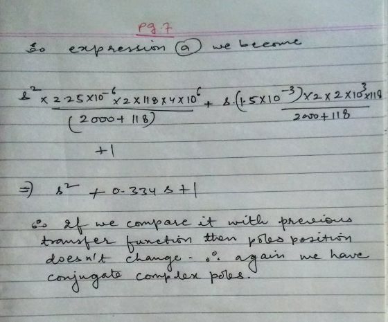
c) Consider a broadband bandpass op amp filter with center
frequency 2.4 kHz and bandwidth 800 Hz. Are the specifications
reasonable and would the transfer function poles be real,
imaginary, or complex?
Homework Answers


Add Answer to:
Design an active unity-gain bandpass filter with
center frequency 750 Hz and bandwidtg 250 Hz and...
Design a bandpass filter, using a cascade connection, to give a center frequency of 600 Hz,...
 Design a bandpass filter, using a cascade connection, to give a center frequency of 600 Hz, a bandwidth of 2 kHz, and a passband gain of 4. Use 250 nF capacitors. Part A Specify fal Express your answer to three significant figures and include the appropriate units. Part B Specify f2. Express your answer to three significant figures and include the appropriate units. Part C Specify RL Express your answer to three significant figures and include the appropriate units. Part...
Finally, design a bandpass filter using this type of filter, with anfo 1500 Hz, and a...
 Finally, design a bandpass filter using this type of filter, with anfo 1500 Hz, and a bandwidth, BW 150 Hz. What is the gain at the center frequency for your design? Ry C2
Problem 4 Use a 5 nF capacitor to design a series RLC bandpass filter. The center...
 Problem 4 Use a 5 nF capacitor to design a series RLC bandpass filter. The center frequency the filter is 8 kHz, and the quality factor is 1.5. Part A Specify the value of L. View Available Hint(s) EVO AQH vec ? L = 0.079 ml Submit Previous Answers * Incorrect; Try Again; 8 attempts remaining Part B Specify the value of R. 10 AEDIf vec ? R = k12 Submit Request Answer Problem 4 Use a 5 nF capacitor...
1. Design a parallel RLC bandpass filter, derive the transfer function H(s). Compute the center frequency, Wo. Calculate the cutoff frequencies Wej and Wc2, the bandwidth ß, and quality factor, Q. Co...
 1. Design a parallel RLC bandpass filter, derive the transfer function H(s). Compute the center frequency, Wo. Calculate the cutoff frequencies Wej and Wc2, the bandwidth ß, and quality factor, Q. Compute values for R and L to yield a bandpass filter with a center frequency of 5kHz and a bandwidth of 200Hz, using a 10nF capacitor. (25 points)
1. Design a parallel RLC bandpass filter, derive the transfer function H(s). Compute the center frequency, Wo. Calculate the cutoff frequencies...
1. Design a parallel RLC bandpass filter, derive the transfer function H(s). Compute the center frequency, Wo. Calculate the cutoff frequencies Wej and Wc2, the bandwidth ß, and quality factor, Q. Compute values for R and L to yield a bandpass filter with a center frequency of 5kHz and a bandwidth of 200Hz, using a 10nF capacitor. (25 points)
1. Design a parallel RLC bandpass filter, derive the transfer function H(s). Compute the center frequency, Wo. Calculate the cutoff frequencies...
Design an active band-pass filter such that the center frequency is Fo-2.5 kHz, bandwidth is BW...
 Design an active band-pass filter such that the center frequency is Fo-2.5 kHz, bandwidth is BW 400 Hz and gain is K-3 for Figure 10.5. Find the values for the capacitors, and resistors. Compute the theoretical values of Vout and |Av Vout / V l and record the results in Table 10.5-A. VEE -15V C1 R3 C2 R1 R2 Vout +VCC +15V Figure 10.5
13.60 A second-order band-pass filter is required with a center frequency of fo 54 kHz and a pass...
 13.60 A second-order band-pass filter is required with a center frequency of fo 54 kHz and a passband gain of +50 dB. If the filter is implemented using the circuit of Fig. 13.15 with C1-C2, choose appropriate values for Ri and R2. What is the resulting value of for the filter? What is its bandwidth? Ci Figure 13.15 Second-order active bandpass filter of the Sallen-Key type. R2 C2 Ri UIN OUT
13.60 A second-order band-pass filter is required with a...
13.60 A second-order band-pass filter is required with a center frequency of fo 54 kHz and a passband gain of +50 dB. If the filter is implemented using the circuit of Fig. 13.15 with C1-C2, choose appropriate values for Ri and R2. What is the resulting value of for the filter? What is its bandwidth? Ci Figure 13.15 Second-order active bandpass filter of the Sallen-Key type. R2 C2 Ri UIN OUT
13.60 A second-order band-pass filter is required with a...
BPF Filter Bandpass Filter The following circuit acts as a C This filter has a center...
 BPF Filter Bandpass Filter The following circuit acts as a C This filter has a center (resonance) frequency at Hz. 27-VLC and a 3-dB bandwidth of BW = Hz. 2RC 3l f, and a passband for which the signal is This means that the filter has 0 dB gain at attenuated less than 3 dB centered approximately at f, from f,-BW2 to f.+BW/2 (this passband is not exactly centered at f, but its total width is BW) 3l8 Input Signal...
QI (a) () Design an active filter using non-inverting amplifier that will produce a frequency response...
 QI (a) () Design an active filter using non-inverting amplifier that will produce a frequency response as shown in Figure Ql(a). The bandwidth of the filter is 30 kHz. Use a capacitor value of 10 nF. (9 marks) Draw the circuit and clearly label it. (5 marks) (b) Derive the transfer function of the filter in Q1(b). (6 marks) Av (dB) 28 dB 25 dB - 20 dB/decade + 20 dB/decade - 1 1 35 kHz 40 kHz Figure Qi(a)...
EXAMPLE 1: Design a fifth-order lowpass Butterworth filter with a dc gain equal to unity and the half-power frequency at i kHz. Make the largest capacitance is 1 μF. EXAMPLE 1: Design a fifth-or...
 EXAMPLE 1: Design a fifth-order lowpass Butterworth filter with a dc gain equal to unity and the half-power frequency at i kHz. Make the largest capacitance is 1 μF.
EXAMPLE 1: Design a fifth-order lowpass Butterworth filter with a dc gain equal to unity and the half-power frequency at i kHz. Make the largest capacitance is 1 μF.
EXAMPLE 1: Design a fifth-order lowpass Butterworth filter with a dc gain equal to unity and the half-power frequency at i kHz. Make the largest capacitance is 1 μF.
(14%) 6. Consider an FM modulator with output )-100 cos(2(1000)r+(0) The modulator operates with fa = 8 and has the input message signal The modulator is followed by a bandpass filter with a...
 (14%) 6. Consider an FM modulator with output )-100 cos(2(1000)r+(0) The modulator operates with fa = 8 and has the input message signal The modulator is followed by a bandpass filter with a a bandwidth of 56HZ, as shown in the following figure. Determine the power ratio and the power at the fiter oput center frequency of 1000HZ and Bandpass filter PM Output Center 1000 Hz Bandwidth 56 Hz mt-5 cos 2(8)r modulator -1000 Hz (a) FM system 39.1 39.1365...
 Design a bandpass filter, using a cascade connection, to give a center frequency of 600 Hz, a bandwidth of 2 kHz, and a passband gain of 4. Use 250 nF capacitors. Part A Specify fal Express your answer to three significant figures and include the appropriate units. Part B Specify f2. Express your answer to three significant figures and include the appropriate units. Part C Specify RL Express your answer to three significant figures and include the appropriate units. Part...
 Finally, design a bandpass filter using this type of filter, with anfo 1500 Hz, and a bandwidth, BW 150 Hz. What is the gain at the center frequency for your design? Ry C2
 Problem 4 Use a 5 nF capacitor to design a series RLC bandpass filter. The center frequency the filter is 8 kHz, and the quality factor is 1.5. Part A Specify the value of L. View Available Hint(s) EVO AQH vec ? L = 0.079 ml Submit Previous Answers * Incorrect; Try Again; 8 attempts remaining Part B Specify the value of R. 10 AEDIf vec ? R = k12 Submit Request Answer Problem 4 Use a 5 nF capacitor...
 1. Design a parallel RLC bandpass filter, derive the transfer function H(s). Compute the center frequency, Wo. Calculate the cutoff frequencies Wej and Wc2, the bandwidth ß, and quality factor, Q. Compute values for R and L to yield a bandpass filter with a center frequency of 5kHz and a bandwidth of 200Hz, using a 10nF capacitor. (25 points)
1. Design a parallel RLC bandpass filter, derive the transfer function H(s). Compute the center frequency, Wo. Calculate the cutoff frequencies...
1. Design a parallel RLC bandpass filter, derive the transfer function H(s). Compute the center frequency, Wo. Calculate the cutoff frequencies Wej and Wc2, the bandwidth ß, and quality factor, Q. Compute values for R and L to yield a bandpass filter with a center frequency of 5kHz and a bandwidth of 200Hz, using a 10nF capacitor. (25 points)
1. Design a parallel RLC bandpass filter, derive the transfer function H(s). Compute the center frequency, Wo. Calculate the cutoff frequencies...
 Design an active band-pass filter such that the center frequency is Fo-2.5 kHz, bandwidth is BW 400 Hz and gain is K-3 for Figure 10.5. Find the values for the capacitors, and resistors. Compute the theoretical values of Vout and |Av Vout / V l and record the results in Table 10.5-A. VEE -15V C1 R3 C2 R1 R2 Vout +VCC +15V Figure 10.5
 13.60 A second-order band-pass filter is required with a center frequency of fo 54 kHz and a passband gain of +50 dB. If the filter is implemented using the circuit of Fig. 13.15 with C1-C2, choose appropriate values for Ri and R2. What is the resulting value of for the filter? What is its bandwidth? Ci Figure 13.15 Second-order active bandpass filter of the Sallen-Key type. R2 C2 Ri UIN OUT
13.60 A second-order band-pass filter is required with a...
13.60 A second-order band-pass filter is required with a center frequency of fo 54 kHz and a passband gain of +50 dB. If the filter is implemented using the circuit of Fig. 13.15 with C1-C2, choose appropriate values for Ri and R2. What is the resulting value of for the filter? What is its bandwidth? Ci Figure 13.15 Second-order active bandpass filter of the Sallen-Key type. R2 C2 Ri UIN OUT
13.60 A second-order band-pass filter is required with a...
 BPF Filter Bandpass Filter The following circuit acts as a C This filter has a center (resonance) frequency at Hz. 27-VLC and a 3-dB bandwidth of BW = Hz. 2RC 3l f, and a passband for which the signal is This means that the filter has 0 dB gain at attenuated less than 3 dB centered approximately at f, from f,-BW2 to f.+BW/2 (this passband is not exactly centered at f, but its total width is BW) 3l8 Input Signal...
 QI (a) () Design an active filter using non-inverting amplifier that will produce a frequency response as shown in Figure Ql(a). The bandwidth of the filter is 30 kHz. Use a capacitor value of 10 nF. (9 marks) Draw the circuit and clearly label it. (5 marks) (b) Derive the transfer function of the filter in Q1(b). (6 marks) Av (dB) 28 dB 25 dB - 20 dB/decade + 20 dB/decade - 1 1 35 kHz 40 kHz Figure Qi(a)...
 EXAMPLE 1: Design a fifth-order lowpass Butterworth filter with a dc gain equal to unity and the half-power frequency at i kHz. Make the largest capacitance is 1 μF.
EXAMPLE 1: Design a fifth-order lowpass Butterworth filter with a dc gain equal to unity and the half-power frequency at i kHz. Make the largest capacitance is 1 μF.
EXAMPLE 1: Design a fifth-order lowpass Butterworth filter with a dc gain equal to unity and the half-power frequency at i kHz. Make the largest capacitance is 1 μF.
 (14%) 6. Consider an FM modulator with output )-100 cos(2(1000)r+(0) The modulator operates with fa = 8 and has the input message signal The modulator is followed by a bandpass filter with a a bandwidth of 56HZ, as shown in the following figure. Determine the power ratio and the power at the fiter oput center frequency of 1000HZ and Bandpass filter PM Output Center 1000 Hz Bandwidth 56 Hz mt-5 cos 2(8)r modulator -1000 Hz (a) FM system 39.1 39.1365...
Most questions answered within 3 hours.
-
A regression equation that describes the relationship between
the amount of the bill ($) at a...
asked 45 minutes ago -
exercise on VSEPR and molecular structrue.
octahedral
SeCl62-
TeCl62-
ClF62-
distorted
SeF62–
IF6–
asked 1 hour ago -
284 mL of a 0.52 M potassium hydroxide solution is added to 467
mL of a...
asked 1 hour ago -
Little’s Law: Val d’Costa is a world famous ski village in the
French Alps. Because of...
asked 2 hours ago -
Find the absolute error D for the calculation if A + B/C=D A=
9.4 +/- 0.4...
asked 2 hours ago -
New Air Heating and Cooling, manufactures furnaces and central
air units. The company pride itself on...
asked 2 hours ago -
A coach uses a new technique to train gymnasts. Seven
gymnasts were randomly selected and their...
asked 4 hours ago -
While rotating the tires on your car you notice a rock [mass =
0.1 Kg] stuck...
asked 6 hours ago -
Using MARS simulator, write MIPS programs according to
the following scenarios: Receive a positive integer number...
asked 8 hours ago -
An object in front of a concave mirror has a real image that is
11.5 cm...
asked 8 hours ago -
Consider the reaction, C3 H8 + O2 --> CO2 + H2O. How many
moles of O2...
asked 10 hours ago -
You and your opponent both roll a fair die. If you both roll the
same number,...
asked 10 hours ago