
Homework Answers

Add Answer to:
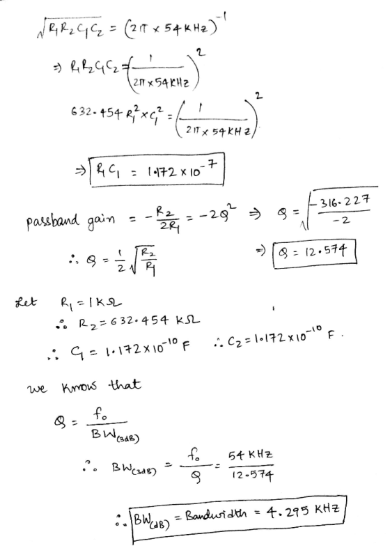
13.60 A second-order band-pass filter is required with a center frequency of fo 54 kHz and a pass...
Design an active band-pass filter such that the center frequency is Fo-2.5 kHz, bandwidth is BW...
 Design an active band-pass filter such that the center frequency is Fo-2.5 kHz, bandwidth is BW 400 Hz and gain is K-3 for Figure 10.5. Find the values for the capacitors, and resistors. Compute the theoretical values of Vout and |Av Vout / V l and record the results in Table 10.5-A. VEE -15V C1 R3 C2 R1 R2 Vout +VCC +15V Figure 10.5
Design a low-pass filter (LPF) has pass-band frequency fP = 100 kHz, maximum attenuation in passband Amax = 2 dB, stop-band frequency fS = 120 kHz, minimum attenuation in stop-band Amin = 60 dB.
 Design a low-pass filter (LPF) has pass-band frequency fP = 100 kHz, maximum attenuation in passband Amax
= 2 dB, stop-band frequency fS = 120 kHz, minimum attenuation in stop-band Amin = 60 dB. a/ Calculate the minimum order N for Chebyshev filter and the corresponding minimum stop-band
attenuation? b/ Calculate the minimum order N of low-pass B
Design a low-pass filter (LPF) has pass-band frequency fP = 100 kHz, maximum attenuation in passband Amax
= 2 dB, stop-band frequency fS = 120 kHz, minimum attenuation in stop-band Amin = 60 dB. a/ Calculate the minimum order N for Chebyshev filter and the corresponding minimum stop-band
attenuation? b/ Calculate the minimum order N of low-pass B
5) Consider the following second-order bandpass filter. As input voltage, apply V(t) 100Ω, C-4.7 μF. and L-10mH. sin(wt).R in Vout Fig 9: Second-order band-pass filter a) Determine the frequenc...
 5) Consider the following second-order bandpass filter. As input voltage, apply V(t) 100Ω, C-4.7 μF. and L-10mH. sin(wt).R in Vout Fig 9: Second-order band-pass filter a) Determine the frequency response function H(ju) Ve-ju) / Vm(ju) and sketch the magnitude and phase characteristics versus w by calaulation. Calculate the theoretical cutoff frequency of the filter Using PSpice AC analysis, plot magnitude lHju)l and phase ф characteristics of the filter, between 1 Hz-100 KHz b) c)
5) Consider the following second-order bandpass...
5) Consider the following second-order bandpass filter. As input voltage, apply V(t) 100Ω, C-4.7 μF. and L-10mH. sin(wt).R in Vout Fig 9: Second-order band-pass filter a) Determine the frequency response function H(ju) Ve-ju) / Vm(ju) and sketch the magnitude and phase characteristics versus w by calaulation. Calculate the theoretical cutoff frequency of the filter Using PSpice AC analysis, plot magnitude lHju)l and phase ф characteristics of the filter, between 1 Hz-100 KHz b) c)
5) Consider the following second-order bandpass...
Create a 4th-order lowpass active Chebyshev filter with a 3-dB ripple in the pass band with...
Create a 4th-order lowpass active Chebyshev filter with a 3-dB ripple in the pass band with a corner frequency of 250 Hz using the Sallen-Key topology. Draw the final circuit and all component values. Create a Bode plot for the response at each stage and the overall response using MATLAB
QUESTION 1 Design a second order passive low-pass filter that has a cutoff frequency of 6...
 QUESTION 1 Design a second order passive low-pass filter that has a cutoff frequency of 6 KHz by: a. Choosing an appropriate R and C value. (HINT: R1=R2=10K and C1=C2=C) A= C/S V=J/C V=AN 1 H2 = 1/5 F = CN Final Solution: C1=
A) Design a low-pass filter using the given circuitry with a cut-off value of 1 kHz and plot the ...
 a) Design a low-pass filter using the given circuitry with a cut-off value of 1 kHz and plot the frequency response curve on the given axes 1.0 0.7 0.5 in out 0.0 101 102 103 104 10s Hz b) Design a band-pass filter using the given circuitry with a bandwidth of 500 Hz and a lower cut-off value of 100 Hz, and draw the frequency response curve. Keep all resistors at the same value (i.e. Ri-R-R3-R4). 1.0 0.7 0.5 0.0...
Design a -40 dB second order low pass active filter for a cut-off frequency of 3...
Design a -40 dB second order low pass active filter for a cut-off frequency of 3 kHz. You are free to choose the values of resistors and capacitors.
Design a second-order high pass active filter with a cutoff frequency of 1Hz and a passband...
Design a second-order high pass active filter with a cutoff frequency of 1Hz and a passband gain of 10. Show all calculations and provide a schematic of your design.
53. A 2- order normalized Butterworth filter can be improved by using a so-called Chebeyshev filter...
 53. A 2- order normalized Butterworth filter can be improved by using a so-called Chebeyshev filter The 3dBNLP second order NLP Chebeyshev transfer function is: 0.5012 2 +0.6449s+0.7079 Cheb3dBNLP(s) The Chebeyshev filter has some ripple in the passband but has better roll off, more attenuation in the stop band. If one can tolerate some ripple (sort of like a bouncy car ride) in the passband Chebeyshev filters typically have lower order than Butterworth filters. But, Butterworth filters have NO ripple...
Design a parallel RLC band-pass filter to have the nominal center frequency f0 = 280 kHz and the 3dB bandwidth B = 7.9 k...
Design a parallel RLC band-pass filter to have the nominal center frequency f0 = 280 kHz and the 3dB bandwidth B = 7.9 kHz. Use only single, standard-valued components: 5% resistors, 10% capacitors and 10% IMS-5WD-40 inductors. Assume that inductor's Q is constant in the frequency range [0.1 - 1.0]ft, where ft is the 'TEST FREQUENCY Q' given in the IMS-5WD-40 data sheet. L = C = R =
 Design an active band-pass filter such that the center frequency is Fo-2.5 kHz, bandwidth is BW 400 Hz and gain is K-3 for Figure 10.5. Find the values for the capacitors, and resistors. Compute the theoretical values of Vout and |Av Vout / V l and record the results in Table 10.5-A. VEE -15V C1 R3 C2 R1 R2 Vout +VCC +15V Figure 10.5
 5) Consider the following second-order bandpass filter. As input voltage, apply V(t) 100Ω, C-4.7 μF. and L-10mH. sin(wt).R in Vout Fig 9: Second-order band-pass filter a) Determine the frequency response function H(ju) Ve-ju) / Vm(ju) and sketch the magnitude and phase characteristics versus w by calaulation. Calculate the theoretical cutoff frequency of the filter Using PSpice AC analysis, plot magnitude lHju)l and phase ф characteristics of the filter, between 1 Hz-100 KHz b) c)
5) Consider the following second-order bandpass...
5) Consider the following second-order bandpass filter. As input voltage, apply V(t) 100Ω, C-4.7 μF. and L-10mH. sin(wt).R in Vout Fig 9: Second-order band-pass filter a) Determine the frequency response function H(ju) Ve-ju) / Vm(ju) and sketch the magnitude and phase characteristics versus w by calaulation. Calculate the theoretical cutoff frequency of the filter Using PSpice AC analysis, plot magnitude lHju)l and phase ф characteristics of the filter, between 1 Hz-100 KHz b) c)
5) Consider the following second-order bandpass...
 QUESTION 1 Design a second order passive low-pass filter that has a cutoff frequency of 6 KHz by: a. Choosing an appropriate R and C value. (HINT: R1=R2=10K and C1=C2=C) A= C/S V=J/C V=AN 1 H2 = 1/5 F = CN Final Solution: C1=
 a) Design a low-pass filter using the given circuitry with a cut-off value of 1 kHz and plot the frequency response curve on the given axes 1.0 0.7 0.5 in out 0.0 101 102 103 104 10s Hz b) Design a band-pass filter using the given circuitry with a bandwidth of 500 Hz and a lower cut-off value of 100 Hz, and draw the frequency response curve. Keep all resistors at the same value (i.e. Ri-R-R3-R4). 1.0 0.7 0.5 0.0...
 53. A 2- order normalized Butterworth filter can be improved by using a so-called Chebeyshev filter The 3dBNLP second order NLP Chebeyshev transfer function is: 0.5012 2 +0.6449s+0.7079 Cheb3dBNLP(s) The Chebeyshev filter has some ripple in the passband but has better roll off, more attenuation in the stop band. If one can tolerate some ripple (sort of like a bouncy car ride) in the passband Chebeyshev filters typically have lower order than Butterworth filters. But, Butterworth filters have NO ripple...
Most questions answered within 3 hours.
-
Write a program to solve the Josephus problem, with the following
modification:
Sample Input:
./a.out n...
asked 17 minutes ago -
At the start of a CD it is spinning at a rate of 525 rpm
(revolutions...
asked 52 minutes ago -
4. Without doing any calculations, predict whether the observed
∆T would increase, decrease or remain the...
asked 2 hours ago -
Based on the range, which of the following sets of scores has
the greatest variability? 3,...
asked 3 hours ago -
Ripples in a pond travel at a velocity of 3 m/s with one peak
passing a...
asked 3 hours ago -
A man stands on the roof of a building of height 13.0 mm and
throws a...
asked 3 hours ago -
The extent to which assets are financed by borrowed funds and
other liabilities is indicated by:...
asked 4 hours ago -
Explain in detail
Germany is the fifth largest economy
explain what goods and services Germany specializes...
asked 4 hours ago -
The density of platinum is 21.45 g/mL. If a cube of platinum
with a mass of...
asked 4 hours ago -
Accounts Receivable
Sales
A/R Posting
Extended Sales Invoice
Packing Slip
Compare invoice to packing slip 2...
asked 4 hours ago -
Michaella, age 23, is a full-time law student and is claimed by
her parents as a...
asked 4 hours ago -
Why are polymers not typically casted into products?
asked 4 hours ago