
Homework Answers


Any doubts leave them in comments. please don't forget to like.
Add Answer to:
A) Design a low-pass filter using the given circuitry with a cut-off value of 1 kHz and plot the ...
Active Low-pass and High-pass Filters for Crossover Circuitry (PSPICE) Design a first order active high-pass filter...
 Active Low-pass and High-pass Filters for Crossover Circuitry
(PSPICE)
Design a first order active high-pass filter with cut-off
frequency of 1 kHz & gain 20dB.
Design a first order active low-pass filter with cut-off
frequency of 1 kHz & gain 20dB.
Plot the magnitude and phase responses of the active high-pass
and low-pass filters you have designed using PSpice (Use UA741 Op
amp and ±12V dual supply).
Connect your active low-pass and high-pass filters as shown in
Fig. 1-b. Assume...
Active Low-pass and High-pass Filters for Crossover Circuitry
(PSPICE)
Design a first order active high-pass filter with cut-off
frequency of 1 kHz & gain 20dB.
Design a first order active low-pass filter with cut-off
frequency of 1 kHz & gain 20dB.
Plot the magnitude and phase responses of the active high-pass
and low-pass filters you have designed using PSpice (Use UA741 Op
amp and ±12V dual supply).
Connect your active low-pass and high-pass filters as shown in
Fig. 1-b. Assume...
c) Dr. Lee collects the signal of the strain gauge above with the sampling frequency 100...
 c) Dr. Lee collects the signal of the strain gauge above with the sampling frequency 100 kHz. He is interested in the data within the following frequency range: 1-10 kHz. Design the 2nd order filter system and draw the frequency response curve. Hint: assume Ri-R2 R3-R4 1.0 C4 R2 RA 0.7 3 0.5 0.0 101 102 103 10. 105 Hz
Using the windowing functions discussed in class, design a low-pass FIR filter with a cutoff freq...
 Using the windowing functions discussed in class, design a
low-pass FIR filter with a cutoff frequency of 2 kHz, a minimum
stop band attenuation of 40 dB, and a transition width of 200Hz.
The sampling frequency is 10kHz.
1. Using the windowing functions discussed in class, design a low-pass FIR filter with a cutoff frequency of 2 kHz, a minimum stop band attenuation of 40 dB, and a transition width of 200 Hz. The sampling frequency is 10 kHz 2....
Using the windowing functions discussed in class, design a
low-pass FIR filter with a cutoff frequency of 2 kHz, a minimum
stop band attenuation of 40 dB, and a transition width of 200Hz.
The sampling frequency is 10kHz.
1. Using the windowing functions discussed in class, design a low-pass FIR filter with a cutoff frequency of 2 kHz, a minimum stop band attenuation of 40 dB, and a transition width of 200 Hz. The sampling frequency is 10 kHz 2....
Design a -40 dB second order low pass active filter for a cut-off frequency of 3...
Design a -40 dB second order low pass active filter for a cut-off frequency of 3 kHz. You are free to choose the values of resistors and capacitors.
Signal And System Build a first order LPF with cut-off frequency at 10 kHz. A simple...
 Signal And System
Build a first order LPF with cut-off frequency at 10 kHz. A simple low pass filter (first order) circuit is shown in Figure 1. V = gain 0.7 (a) RC low Pass Filter Circuit Figure 1 (b) Frequency ResponseCurve show that the impulse response for a first order low-pass filter in Figure 1 is given by 1 H(f) = 1+j295RC The cut-off frequency for a low-pass filter is fcutoff ZRC Generate a rectangular pulse with frequency of...
Signal And System
Build a first order LPF with cut-off frequency at 10 kHz. A simple low pass filter (first order) circuit is shown in Figure 1. V = gain 0.7 (a) RC low Pass Filter Circuit Figure 1 (b) Frequency ResponseCurve show that the impulse response for a first order low-pass filter in Figure 1 is given by 1 H(f) = 1+j295RC The cut-off frequency for a low-pass filter is fcutoff ZRC Generate a rectangular pulse with frequency of...
Explain your process please 1. Design 6th order Butterworth band-pass filter with cut-off frequency is 4KHz...
 Explain your process please
1. Design 6th order Butterworth band-pass filter with cut-off frequency is 4KHz and 7KHz and pass- band gain is 20dB Draw the circuit, write the transfer function of the filter, and sketch a frequency spectrum of the filter and show the cutoff frequencies on the spectrum Solution:
Explain your process please
1. Design 6th order Butterworth band-pass filter with cut-off frequency is 4KHz and 7KHz and pass- band gain is 20dB Draw the circuit, write the transfer function of the filter, and sketch a frequency spectrum of the filter and show the cutoff frequencies on the spectrum Solution:
QuestionThree useful circuit combinations in AC circuits are high-pass,"low-pass," and band-pass" filters. In the first case,...
 QuestionThree useful circuit combinations in AC circuits are
high-pass,"low-pass," and band-pass" filters. In the first case,
high frequency signals are allow to through the filter while low
frequencies are not while the opposite is true in the second case.
The third case allows Jonly limited region of frequencies through
the filter. Examine the series RLC circuit and iden tify what
behaves in the circuit like the different filter
combinations.
0.8 H 0000 Reactance XL (12) W 1.0 kN2 100 101...
QuestionThree useful circuit combinations in AC circuits are
high-pass,"low-pass," and band-pass" filters. In the first case,
high frequency signals are allow to through the filter while low
frequencies are not while the opposite is true in the second case.
The third case allows Jonly limited region of frequencies through
the filter. Examine the series RLC circuit and iden tify what
behaves in the circuit like the different filter
combinations.
0.8 H 0000 Reactance XL (12) W 1.0 kN2 100 101...
Design a fourth order low pass Butterworth filter with a cutoff frequency of 2 kHz and...
Design a fourth order low pass Butterworth filter with a cutoff frequency of 2 kHz and draw the frequency response for the filter.
Design a low pass filter with a cutoff frequency of 1 kHz +/- 100 Hz and...
Design a low pass filter with a cutoff frequency of 1 kHz +/- 100 Hz and a gain of 16.0 dB +/- 1.0 dB in the passband. The R2 and C components of the filter control the cutoff frequency, and are inversely proportional to the cutoff frequency. So decreasing the resistance or capacitance will increase the cutoff frequency. The R1 and Rf components determine the gain of the amplifier. Increasing the value of Rf will increase the gain. Increasing the...
2. By applying Bode plot approximations, sketch the response of each filter, and hence complete the Table below. Filter Type Order Cut-off Frequency High Passsecond 120kHz Low Pass fourth 2250Hz 400H...
 2. By applying Bode plot approximations, sketch the response of each filter, and hence complete the Table below. Filter Type Order Cut-off Frequency High Passsecond 120kHz Low Pass fourth 2250Hz 400Hz Gain in Stop Band Pass-Band Gain OdB Gain at 15kHz Gain at 18kHz = ? Gain at 50Hz-18dB Gain at 15Hz = ? Gain at 64kHz ? Gain -60dB at 50kH:z 6dB OdB OdB High Pass Band Pass fourth 60Hz, 4kHz 12dB Low Pass sixth 1?
2. By applying...
2. By applying Bode plot approximations, sketch the response of each filter, and hence complete the Table below. Filter Type Order Cut-off Frequency High Passsecond 120kHz Low Pass fourth 2250Hz 400Hz Gain in Stop Band Pass-Band Gain OdB Gain at 15kHz Gain at 18kHz = ? Gain at 50Hz-18dB Gain at 15Hz = ? Gain at 64kHz ? Gain -60dB at 50kH:z 6dB OdB OdB High Pass Band Pass fourth 60Hz, 4kHz 12dB Low Pass sixth 1?
2. By applying...
 Active Low-pass and High-pass Filters for Crossover Circuitry
(PSPICE)
Design a first order active high-pass filter with cut-off
frequency of 1 kHz & gain 20dB.
Design a first order active low-pass filter with cut-off
frequency of 1 kHz & gain 20dB.
Plot the magnitude and phase responses of the active high-pass
and low-pass filters you have designed using PSpice (Use UA741 Op
amp and ±12V dual supply).
Connect your active low-pass and high-pass filters as shown in
Fig. 1-b. Assume...
Active Low-pass and High-pass Filters for Crossover Circuitry
(PSPICE)
Design a first order active high-pass filter with cut-off
frequency of 1 kHz & gain 20dB.
Design a first order active low-pass filter with cut-off
frequency of 1 kHz & gain 20dB.
Plot the magnitude and phase responses of the active high-pass
and low-pass filters you have designed using PSpice (Use UA741 Op
amp and ±12V dual supply).
Connect your active low-pass and high-pass filters as shown in
Fig. 1-b. Assume...
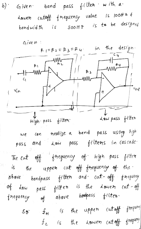
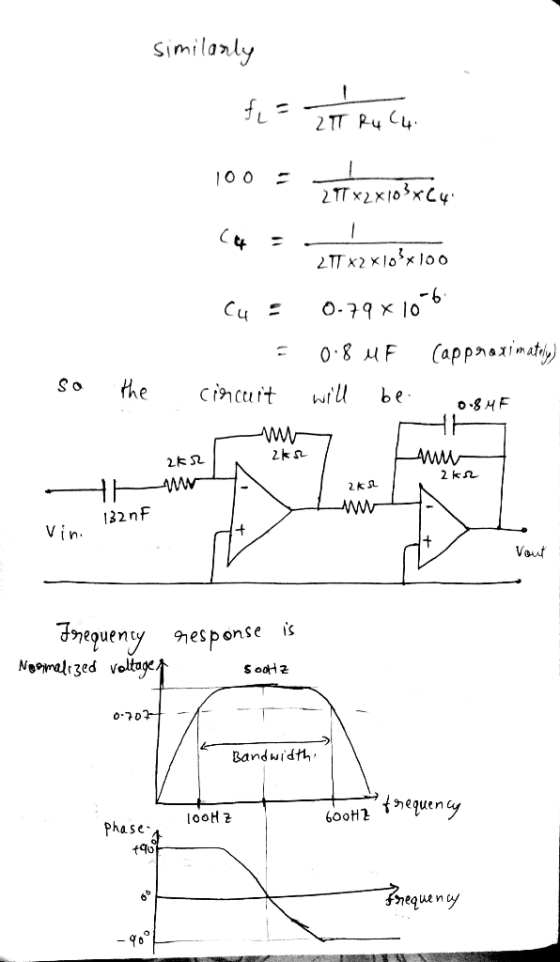
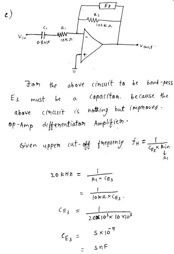
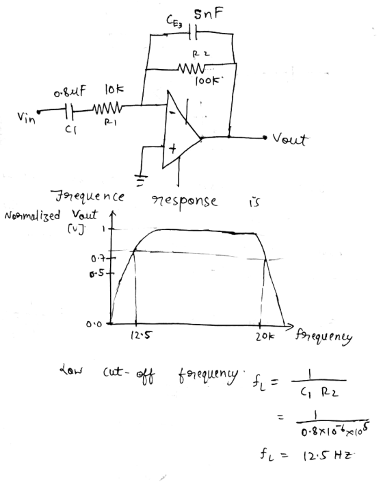
 c) Dr. Lee collects the signal of the strain gauge above with the sampling frequency 100 kHz. He is interested in the data within the following frequency range: 1-10 kHz. Design the 2nd order filter system and draw the frequency response curve. Hint: assume Ri-R2 R3-R4 1.0 C4 R2 RA 0.7 3 0.5 0.0 101 102 103 10. 105 Hz
 Using the windowing functions discussed in class, design a
low-pass FIR filter with a cutoff frequency of 2 kHz, a minimum
stop band attenuation of 40 dB, and a transition width of 200Hz.
The sampling frequency is 10kHz.
1. Using the windowing functions discussed in class, design a low-pass FIR filter with a cutoff frequency of 2 kHz, a minimum stop band attenuation of 40 dB, and a transition width of 200 Hz. The sampling frequency is 10 kHz 2....
Using the windowing functions discussed in class, design a
low-pass FIR filter with a cutoff frequency of 2 kHz, a minimum
stop band attenuation of 40 dB, and a transition width of 200Hz.
The sampling frequency is 10kHz.
1. Using the windowing functions discussed in class, design a low-pass FIR filter with a cutoff frequency of 2 kHz, a minimum stop band attenuation of 40 dB, and a transition width of 200 Hz. The sampling frequency is 10 kHz 2....
 Signal And System
Build a first order LPF with cut-off frequency at 10 kHz. A simple low pass filter (first order) circuit is shown in Figure 1. V = gain 0.7 (a) RC low Pass Filter Circuit Figure 1 (b) Frequency ResponseCurve show that the impulse response for a first order low-pass filter in Figure 1 is given by 1 H(f) = 1+j295RC The cut-off frequency for a low-pass filter is fcutoff ZRC Generate a rectangular pulse with frequency of...
Signal And System
Build a first order LPF with cut-off frequency at 10 kHz. A simple low pass filter (first order) circuit is shown in Figure 1. V = gain 0.7 (a) RC low Pass Filter Circuit Figure 1 (b) Frequency ResponseCurve show that the impulse response for a first order low-pass filter in Figure 1 is given by 1 H(f) = 1+j295RC The cut-off frequency for a low-pass filter is fcutoff ZRC Generate a rectangular pulse with frequency of...
 Explain your process please
1. Design 6th order Butterworth band-pass filter with cut-off frequency is 4KHz and 7KHz and pass- band gain is 20dB Draw the circuit, write the transfer function of the filter, and sketch a frequency spectrum of the filter and show the cutoff frequencies on the spectrum Solution:
Explain your process please
1. Design 6th order Butterworth band-pass filter with cut-off frequency is 4KHz and 7KHz and pass- band gain is 20dB Draw the circuit, write the transfer function of the filter, and sketch a frequency spectrum of the filter and show the cutoff frequencies on the spectrum Solution:
 QuestionThree useful circuit combinations in AC circuits are
high-pass,"low-pass," and band-pass" filters. In the first case,
high frequency signals are allow to through the filter while low
frequencies are not while the opposite is true in the second case.
The third case allows Jonly limited region of frequencies through
the filter. Examine the series RLC circuit and iden tify what
behaves in the circuit like the different filter
combinations.
0.8 H 0000 Reactance XL (12) W 1.0 kN2 100 101...
QuestionThree useful circuit combinations in AC circuits are
high-pass,"low-pass," and band-pass" filters. In the first case,
high frequency signals are allow to through the filter while low
frequencies are not while the opposite is true in the second case.
The third case allows Jonly limited region of frequencies through
the filter. Examine the series RLC circuit and iden tify what
behaves in the circuit like the different filter
combinations.
0.8 H 0000 Reactance XL (12) W 1.0 kN2 100 101...
 2. By applying Bode plot approximations, sketch the response of each filter, and hence complete the Table below. Filter Type Order Cut-off Frequency High Passsecond 120kHz Low Pass fourth 2250Hz 400Hz Gain in Stop Band Pass-Band Gain OdB Gain at 15kHz Gain at 18kHz = ? Gain at 50Hz-18dB Gain at 15Hz = ? Gain at 64kHz ? Gain -60dB at 50kH:z 6dB OdB OdB High Pass Band Pass fourth 60Hz, 4kHz 12dB Low Pass sixth 1?
2. By applying...
2. By applying Bode plot approximations, sketch the response of each filter, and hence complete the Table below. Filter Type Order Cut-off Frequency High Passsecond 120kHz Low Pass fourth 2250Hz 400Hz Gain in Stop Band Pass-Band Gain OdB Gain at 15kHz Gain at 18kHz = ? Gain at 50Hz-18dB Gain at 15Hz = ? Gain at 64kHz ? Gain -60dB at 50kH:z 6dB OdB OdB High Pass Band Pass fourth 60Hz, 4kHz 12dB Low Pass sixth 1?
2. By applying...
Most questions answered within 3 hours.
-
The condensate from a steam distillation contains 12.0 g of
compound A and 18.0 g of...
asked 50 minutes ago -
A major economic benefit of fixed exchange rates compared to
floating rates is that
a. the...
asked 58 minutes ago -
1) For this reaction,
SiCl4 (l)+ 2H2O(g) <->
SiO2 (s) + 4HCl (g) DeltaH = -127 KJ...
asked 56 minutes ago -
Which of the following does NOT add to US GDP? A. Saudi Arabia
buys fighter jets...
asked 2 hours ago -
2. Describe market equilibrium in terms of the following
characteristics
d.
How supply and demand interactions...
asked 2 hours ago -
1a. Create a class named Computer
- Separate declaration from implementation (i.e. Header and CPP
files)...
asked 2 hours ago -
A medical researcher
believes that a drug changes the body's temperature. Seven test
subjects are randomly...
asked 3 hours ago -
A call option on Project Cash Flow Consulting Inc.'s stock (PCF)
has a market price of...
asked 3 hours ago -
A study on the latest fad diet claimed that the amounts of
weight lost by all...
asked 3 hours ago -
give examples of how gene expression is inherited to the next
generation?
asked 3 hours ago -
If a project has _________ IRR(s), we should __________ . Assume
this project is competing with...
asked 3 hours ago -
In the figure, a sound of wavelength 0.700 m is emitted
isotropically by point source S....
asked 3 hours ago