Design a second-order high pass active filter with a cutoff frequency of 1Hz and a passband...
- Design a second-order high pass active filter with a cutoff frequency of 1Hz and a passband gain of 10. Show all calculations and provide a schematic of your design.
Homework Answers
![*Pecand Onden High pasa Active frieben: WWW- HHE ...Pasal Band gain Av of the Second Onder filter is itt · Av: 10 (Given] it](http://img.homeworklib.com/questions/5edd4440-d67a-11ea-86b8-25eec8c2c02f.png?x-oss-process=image/resize,w_560)
Add Answer to:
Design a second-order high pass active filter with a cutoff
frequency of 1Hz and a passband...
CIRCUIT ANALYSIS 2. Design a second order high pass filter with a passband gain of 20...
 CIRCUIT ANALYSIS
2. Design a second order high pass filter with a passband gain of 20 dB, and a 3 dB upper cutoff frequency ofS Hz.[D] (40)
CIRCUIT ANALYSIS
2. Design a second order high pass filter with a passband gain of 20 dB, and a 3 dB upper cutoff frequency ofS Hz.[D] (40)
(a) Design a first–order high-pass filter with a cutoff frequency fc = 1.5 kHz and a passband gain |Ao| = 20dB, using a...
(a) Design a first–order high-pass filter with a cutoff frequency fc = 1.5 kHz and a passband gain |Ao| = 20dB, using a capacitor C = 47nF. Include a compensation resistor and determine its value. (b) Sketch the frequency response for the circuit (i.e., magnitude vs. frequency and phase vs. frequency). On the magnitude response plot, indicate the cutoff frequency, bandpass gain, and bandstop rolloff slope. On the phase response plot, indicate the approximate value of the phase angle at...
design an active low pass filter with cutoff frequency of 400 hz and gain of 10...
design an active low pass filter with cutoff frequency of 400 hz and gain of 10 db at dc
Design a first order high-pass Butterworth filter that achieves the following specifications: Cutoff frequency = 770...
Design a first order high-pass Butterworth filter that achieves the following specifications: Cutoff frequency = 770 Hz Stop-band corner frequency = 132 Hz dB slope = 20dB / decade Gain at 132 Hz ≈ -14.9 dB Show working for all determined values of R and C
Design a low pass filter with a cutoff frequency of 1 kHz +/- 100 Hz and...
Design a low pass filter with a cutoff frequency of 1 kHz +/- 100 Hz and a gain of 16.0 dB +/- 1.0 dB in the passband. The R2 and C components of the filter control the cutoff frequency, and are inversely proportional to the cutoff frequency. So decreasing the resistance or capacitance will increase the cutoff frequency. The R1 and Rf components determine the gain of the amplifier. Increasing the value of Rf will increase the gain. Increasing the...
Active Low-pass and High-pass Filters for Crossover Circuitry (PSPICE) Design a first order active high-pass filter...
 Active Low-pass and High-pass Filters for Crossover Circuitry
(PSPICE)
Design a first order active high-pass filter with cut-off
frequency of 1 kHz & gain 20dB.
Design a first order active low-pass filter with cut-off
frequency of 1 kHz & gain 20dB.
Plot the magnitude and phase responses of the active high-pass
and low-pass filters you have designed using PSpice (Use UA741 Op
amp and ±12V dual supply).
Connect your active low-pass and high-pass filters as shown in
Fig. 1-b. Assume...
Active Low-pass and High-pass Filters for Crossover Circuitry
(PSPICE)
Design a first order active high-pass filter with cut-off
frequency of 1 kHz & gain 20dB.
Design a first order active low-pass filter with cut-off
frequency of 1 kHz & gain 20dB.
Plot the magnitude and phase responses of the active high-pass
and low-pass filters you have designed using PSpice (Use UA741 Op
amp and ±12V dual supply).
Connect your active low-pass and high-pass filters as shown in
Fig. 1-b. Assume...
13.6 Design a first-order active high-pass filter with a response of +12 dB in the high-frequency...
 13.6 Design a first-order active high-pass filter with a response of +12 dB in the high-frequency limit and -20 dB at 1.2 kHz. Let C 1 nF
13.6 Design a first-order active high-pass filter with a response of +12 dB in the high-frequency limit and -20 dB at 1.2 kHz. Let C 1 nF
13.6 Design a first-order active high-pass filter with a response of +12 dB in the high-frequency limit and -20 dB at 1.2 kHz. Let C 1 nF
For the low-pass filter circuit shown in Fig 2 3k Ω 200mil in out Fig 2 3.a. Use a 2.2nF capacitor to design a high-pas...
 For the low-pass filter circuit shown in Fig 2 3k Ω 200mil in out Fig 2 3.a. Use a 2.2nF capacitor to design a high-pass filter to have a cutoff frequency of Skn Draw a schematic of your design. Show all component values and voltages c. Sketch the frequency response of the voltage gain and phase shift Magnitude dB Frequency Hz Phase Frequency Hz
For the low-pass filter circuit shown in Fig 2 3k Ω 200mil in out Fig 2...
For the low-pass filter circuit shown in Fig 2 3k Ω 200mil in out Fig 2 3.a. Use a 2.2nF capacitor to design a high-pass filter to have a cutoff frequency of Skn Draw a schematic of your design. Show all component values and voltages c. Sketch the frequency response of the voltage gain and phase shift Magnitude dB Frequency Hz Phase Frequency Hz
For the low-pass filter circuit shown in Fig 2 3k Ω 200mil in out Fig 2...
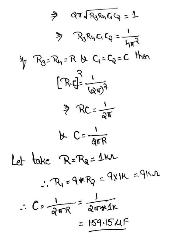
13.60 A second-order band-pass filter is required with a center frequency of fo 54 kHz and a pass...
 13.60 A second-order band-pass filter is required with a center frequency of fo 54 kHz and a passband gain of +50 dB. If the filter is implemented using the circuit of Fig. 13.15 with C1-C2, choose appropriate values for Ri and R2. What is the resulting value of for the filter? What is its bandwidth? Ci Figure 13.15 Second-order active bandpass filter of the Sallen-Key type. R2 C2 Ri UIN OUT
13.60 A second-order band-pass filter is required with a...
13.60 A second-order band-pass filter is required with a center frequency of fo 54 kHz and a passband gain of +50 dB. If the filter is implemented using the circuit of Fig. 13.15 with C1-C2, choose appropriate values for Ri and R2. What is the resulting value of for the filter? What is its bandwidth? Ci Figure 13.15 Second-order active bandpass filter of the Sallen-Key type. R2 C2 Ri UIN OUT
13.60 A second-order band-pass filter is required with a...
Design a second order IIR Butterworth low pass digital filter with a cutoff frequency of 500...
Design a second order IIR Butterworth low pass digital filter with a cutoff frequency of 500 Hz and a sampling frequency of 10,000 Hz using bilinear transformation then find the following: The output (response) due to the following inputs: Sinusoidal signal with a frequency of 100Hz. Sinusoidal signal with a frequency of 500Hz. Sinusoidal signal with a frequency of 2000Hz. Repeat (a) above for a 6thorder Butterworth filter
 CIRCUIT ANALYSIS
2. Design a second order high pass filter with a passband gain of 20 dB, and a 3 dB upper cutoff frequency ofS Hz.[D] (40)
CIRCUIT ANALYSIS
2. Design a second order high pass filter with a passband gain of 20 dB, and a 3 dB upper cutoff frequency ofS Hz.[D] (40)
 Active Low-pass and High-pass Filters for Crossover Circuitry
(PSPICE)
Design a first order active high-pass filter with cut-off
frequency of 1 kHz & gain 20dB.
Design a first order active low-pass filter with cut-off
frequency of 1 kHz & gain 20dB.
Plot the magnitude and phase responses of the active high-pass
and low-pass filters you have designed using PSpice (Use UA741 Op
amp and ±12V dual supply).
Connect your active low-pass and high-pass filters as shown in
Fig. 1-b. Assume...
Active Low-pass and High-pass Filters for Crossover Circuitry
(PSPICE)
Design a first order active high-pass filter with cut-off
frequency of 1 kHz & gain 20dB.
Design a first order active low-pass filter with cut-off
frequency of 1 kHz & gain 20dB.
Plot the magnitude and phase responses of the active high-pass
and low-pass filters you have designed using PSpice (Use UA741 Op
amp and ±12V dual supply).
Connect your active low-pass and high-pass filters as shown in
Fig. 1-b. Assume...
 13.6 Design a first-order active high-pass filter with a response of +12 dB in the high-frequency limit and -20 dB at 1.2 kHz. Let C 1 nF
13.6 Design a first-order active high-pass filter with a response of +12 dB in the high-frequency limit and -20 dB at 1.2 kHz. Let C 1 nF
13.6 Design a first-order active high-pass filter with a response of +12 dB in the high-frequency limit and -20 dB at 1.2 kHz. Let C 1 nF
 For the low-pass filter circuit shown in Fig 2 3k Ω 200mil in out Fig 2 3.a. Use a 2.2nF capacitor to design a high-pass filter to have a cutoff frequency of Skn Draw a schematic of your design. Show all component values and voltages c. Sketch the frequency response of the voltage gain and phase shift Magnitude dB Frequency Hz Phase Frequency Hz
For the low-pass filter circuit shown in Fig 2 3k Ω 200mil in out Fig 2...
For the low-pass filter circuit shown in Fig 2 3k Ω 200mil in out Fig 2 3.a. Use a 2.2nF capacitor to design a high-pass filter to have a cutoff frequency of Skn Draw a schematic of your design. Show all component values and voltages c. Sketch the frequency response of the voltage gain and phase shift Magnitude dB Frequency Hz Phase Frequency Hz
For the low-pass filter circuit shown in Fig 2 3k Ω 200mil in out Fig 2...
 13.60 A second-order band-pass filter is required with a center frequency of fo 54 kHz and a passband gain of +50 dB. If the filter is implemented using the circuit of Fig. 13.15 with C1-C2, choose appropriate values for Ri and R2. What is the resulting value of for the filter? What is its bandwidth? Ci Figure 13.15 Second-order active bandpass filter of the Sallen-Key type. R2 C2 Ri UIN OUT
13.60 A second-order band-pass filter is required with a...
13.60 A second-order band-pass filter is required with a center frequency of fo 54 kHz and a passband gain of +50 dB. If the filter is implemented using the circuit of Fig. 13.15 with C1-C2, choose appropriate values for Ri and R2. What is the resulting value of for the filter? What is its bandwidth? Ci Figure 13.15 Second-order active bandpass filter of the Sallen-Key type. R2 C2 Ri UIN OUT
13.60 A second-order band-pass filter is required with a...
Most questions answered within 3 hours.
-
The length of stay at a specific emergency department in
Phoenix, Arizona, in 2009 had a...
asked 11 seconds ago -
. Please give the mechanism for this type of problem. Step by
Step
The toxin that...
asked 3 minutes ago -
If you have a 1M stock solution and you want to dilute 1 :10
with water,...
asked 5 minutes ago -
In a load instruction, the effective address is obtained by
A) Retriving the address from a...
asked 5 minutes ago -
Use the following information to answer this question.
Windswept, Inc. 2017 Income Statement ($ in millions)...
asked 6 minutes ago -
A mutual fund salesperson has arranged to call on four people
tomorrow. Based on past experience...
asked 39 minutes ago -
Let the RV Y has the pdf
f ( y ) = 6 y ( 1...
asked 51 minutes ago -
Question 12
Where should a copy of a private key should be placed so it is...
asked 8 minutes ago -
What is the entropy change to the surroundings when 1 mol of ice
melts in someone's...
asked 28 minutes ago -
Pt1
An electrochemical cell is set up at 25°C based on the overall
reaction represented by...
asked 34 minutes ago -
Explain traveling wave theory. Explain how the peaking of the
wave leads to action potentials and...
asked 25 minutes ago -
If you mixed 35.0 mLmL of 0.100 M Tris-HCl with 65.0
mLmL of 0.200 M Tris-base, what would...
asked 22 minutes ago