
Homework Answers
Solution:

Add Answer to:
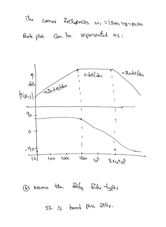
Consider the following transfer function of a bandpass filter: 20 1,500 T(S) = 2 1,500 +...
12.18 Find the transfer function G(0) using the Bode magnitude plot shown below. Hw G/dB) -20...
 12.18 Find the transfer function G(0) using the Bode magnitude plot shown below. Hw G/dB) -20 dB/decade 40 20 100 20 (rad/s) Figure P12.18 12.26 For the following circuit determine the resonant frequency and quality factor. c = 10 nF 2mA R,2k L0.1 mH c
A bode plot of the transfer function, GS = - 25 $2+45+25, is shown as below....
 A bode plot of the transfer function, GS = - 25 $2+45+25, is shown as below. Bode Diagram System sys Frequency (rad/s): 7 Magnitude (dB): -3.4 Magnitude (dB) Phase (deg) Systemt sys Frequency (rad/s): 7 Phase (deg): - 130 - 135 - 180 10 Frequency (rad/s) Determine the frequency response y(t) when a sinusoidal function, X(t) = 10 sin (7t +30) is applied to the transfer function as an input signal. (20 points)
1. Design a parallel RLC bandpass filter, derive the transfer function H(s). Compute the center frequency, Wo. Calculate the cutoff frequencies Wej and Wc2, the bandwidth ß, and quality factor, Q. Co...
 1. Design a parallel RLC bandpass filter, derive the transfer function H(s). Compute the center frequency, Wo. Calculate the cutoff frequencies Wej and Wc2, the bandwidth ß, and quality factor, Q. Compute values for R and L to yield a bandpass filter with a center frequency of 5kHz and a bandwidth of 200Hz, using a 10nF capacitor. (25 points)
1. Design a parallel RLC bandpass filter, derive the transfer function H(s). Compute the center frequency, Wo. Calculate the cutoff frequencies...
1. Design a parallel RLC bandpass filter, derive the transfer function H(s). Compute the center frequency, Wo. Calculate the cutoff frequencies Wej and Wc2, the bandwidth ß, and quality factor, Q. Compute values for R and L to yield a bandpass filter with a center frequency of 5kHz and a bandwidth of 200Hz, using a 10nF capacitor. (25 points)
1. Design a parallel RLC bandpass filter, derive the transfer function H(s). Compute the center frequency, Wo. Calculate the cutoff frequencies...
BPF Filter Bandpass Filter The following circuit acts as a C This filter has a center...
 BPF Filter Bandpass Filter The following circuit acts as a C This filter has a center (resonance) frequency at Hz. 27-VLC and a 3-dB bandwidth of BW = Hz. 2RC 3l f, and a passband for which the signal is This means that the filter has 0 dB gain at attenuated less than 3 dB centered approximately at f, from f,-BW2 to f.+BW/2 (this passband is not exactly centered at f, but its total width is BW) 3l8 Input Signal...
Problem 3. Show that the circuit shown below behaves as a bandpass filter. (Hint-find the transfer...
 Problem 3. Show that the circuit shown below behaves as a bandpass filter. (Hint-find the transfer function for this circuit and show that it has the same form as the transfer function for a bandpass filter. a) Find he center frequency, bandwidth and gain for this bandpass filter. b) Find the cutoff frequencies and the quality for this bandpass filter 10 AF HA 400 SOLF
For the system transfer function given by: s +10 $2 x (82100.+10) 1. Identify each term in the tr...
 For the system transfer function given by: s +10 $2 x (82100.+10) 1. Identify each term in the transfer function (constant, poles, zeros) (a) For any constant terms, what is the dB magnitude? What is the phase angle? (b) For any real poles not at the origin, what is the break frequency? (c) For any real zeros not at the origin, what is the break frequency? 2. Give the value of the DB magnitude and phase angle at w =...
Design an active unity-gain bandpass filter with center frequency 750 Hz and bandwidtg 250 Hz and...
 Design an active unity-gain bandpass filter with
center frequency 750 Hz and bandwidtg 250 Hz and with 0.1 μF
capacitor, R1=6.4kΩ, R2=377Ω, and R3=12.7kΩ.
a)Discuss the circuit response with support of a Bode
magnitude plot.
b) Assume next that a load R_L is connected to the output of the
network at the terminal Vo(s). How does the frequency response of
the loaded configuration change?
c) Consider a broadband bandpass op amp filter with center
frequency 2.4 kHz and bandwidth 800...
Design an active unity-gain bandpass filter with
center frequency 750 Hz and bandwidtg 250 Hz and with 0.1 μF
capacitor, R1=6.4kΩ, R2=377Ω, and R3=12.7kΩ.
a)Discuss the circuit response with support of a Bode
magnitude plot.
b) Assume next that a load R_L is connected to the output of the
network at the terminal Vo(s). How does the frequency response of
the loaded configuration change?
c) Consider a broadband bandpass op amp filter with center
frequency 2.4 kHz and bandwidth 800...
The center frequency is not given. I believe that it must be find based on the body plot. Problem 6:The Bode plot for a passive series RLC bandpass filter is shown in Fig. 2. This filter was built...
 The center frequency is not given. I believe that it must be
find based on the body plot.
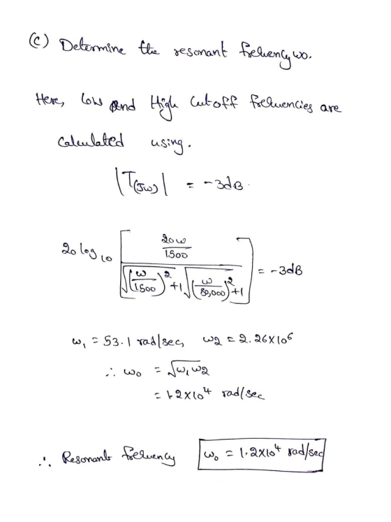
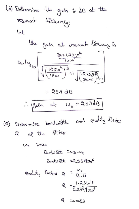
Problem 6:The Bode plot for a passive series RLC bandpass filter is shown in Fig. 2. This filter was built from a 10 μ F capacitor. What is the filter's center frequency, wo, and its quality factor,昱? If you wanted to double the filter's center frequency without changing its quality factor, using the same 10 pu F capacitor, then how would you...
The center frequency is not given. I believe that it must be
find based on the body plot.
Problem 6:The Bode plot for a passive series RLC bandpass filter is shown in Fig. 2. This filter was built from a 10 μ F capacitor. What is the filter's center frequency, wo, and its quality factor,昱? If you wanted to double the filter's center frequency without changing its quality factor, using the same 10 pu F capacitor, then how would you...
PROBLEM 8.1 Consider a bandpass filter specified by the system function 2Swns H (s) = Note that t...
 PROBLEM 8.1 Consider a bandpass filter specified by the system function 2Swns H (s) = Note that the half-power bandwidth of (1) is 2Çwn (a) Figure 1 shows the magnitude squared frequency response for a particular instance of (1) (b) In part (a), you looked at the "horizontal ct of 0.5 on the magnitude squared graph. Let's Find wn and C from the graph look at another cut. Measure the two frequencies on the graph for which the magnitude squared...
For the given transfer function: Ho-2where s 5 (s s (s +10) where s =j w...
 For the given transfer function: Ho-2where s 5 (s s (s +10) where s =j w Sketch the approximate Bode plots (amplitude and phase). Label all the amplitude values in db, phase values in degrees, the slopes in db/dec, and the corner frequencies in rad/sec.. a. b. If the gain of the transfer function given above, H(s), increased by a factor of 10 (from 5 to 50), what will happen to the approximate Bode plots (amplitude and phase) that you...
 12.18 Find the transfer function G(0) using the Bode magnitude plot shown below. Hw G/dB) -20 dB/decade 40 20 100 20 (rad/s) Figure P12.18 12.26 For the following circuit determine the resonant frequency and quality factor. c = 10 nF 2mA R,2k L0.1 mH c
 A bode plot of the transfer function, GS = - 25 $2+45+25, is shown as below. Bode Diagram System sys Frequency (rad/s): 7 Magnitude (dB): -3.4 Magnitude (dB) Phase (deg) Systemt sys Frequency (rad/s): 7 Phase (deg): - 130 - 135 - 180 10 Frequency (rad/s) Determine the frequency response y(t) when a sinusoidal function, X(t) = 10 sin (7t +30) is applied to the transfer function as an input signal. (20 points)
 1. Design a parallel RLC bandpass filter, derive the transfer function H(s). Compute the center frequency, Wo. Calculate the cutoff frequencies Wej and Wc2, the bandwidth ß, and quality factor, Q. Compute values for R and L to yield a bandpass filter with a center frequency of 5kHz and a bandwidth of 200Hz, using a 10nF capacitor. (25 points)
1. Design a parallel RLC bandpass filter, derive the transfer function H(s). Compute the center frequency, Wo. Calculate the cutoff frequencies...
1. Design a parallel RLC bandpass filter, derive the transfer function H(s). Compute the center frequency, Wo. Calculate the cutoff frequencies Wej and Wc2, the bandwidth ß, and quality factor, Q. Compute values for R and L to yield a bandpass filter with a center frequency of 5kHz and a bandwidth of 200Hz, using a 10nF capacitor. (25 points)
1. Design a parallel RLC bandpass filter, derive the transfer function H(s). Compute the center frequency, Wo. Calculate the cutoff frequencies...
 BPF Filter Bandpass Filter The following circuit acts as a C This filter has a center (resonance) frequency at Hz. 27-VLC and a 3-dB bandwidth of BW = Hz. 2RC 3l f, and a passband for which the signal is This means that the filter has 0 dB gain at attenuated less than 3 dB centered approximately at f, from f,-BW2 to f.+BW/2 (this passband is not exactly centered at f, but its total width is BW) 3l8 Input Signal...
 Problem 3. Show that the circuit shown below behaves as a bandpass filter. (Hint-find the transfer function for this circuit and show that it has the same form as the transfer function for a bandpass filter. a) Find he center frequency, bandwidth and gain for this bandpass filter. b) Find the cutoff frequencies and the quality for this bandpass filter 10 AF HA 400 SOLF
 For the system transfer function given by: s +10 $2 x (82100.+10) 1. Identify each term in the transfer function (constant, poles, zeros) (a) For any constant terms, what is the dB magnitude? What is the phase angle? (b) For any real poles not at the origin, what is the break frequency? (c) For any real zeros not at the origin, what is the break frequency? 2. Give the value of the DB magnitude and phase angle at w =...
 Design an active unity-gain bandpass filter with
center frequency 750 Hz and bandwidtg 250 Hz and with 0.1 μF
capacitor, R1=6.4kΩ, R2=377Ω, and R3=12.7kΩ.
a)Discuss the circuit response with support of a Bode
magnitude plot.
b) Assume next that a load R_L is connected to the output of the
network at the terminal Vo(s). How does the frequency response of
the loaded configuration change?
c) Consider a broadband bandpass op amp filter with center
frequency 2.4 kHz and bandwidth 800...
Design an active unity-gain bandpass filter with
center frequency 750 Hz and bandwidtg 250 Hz and with 0.1 μF
capacitor, R1=6.4kΩ, R2=377Ω, and R3=12.7kΩ.
a)Discuss the circuit response with support of a Bode
magnitude plot.
b) Assume next that a load R_L is connected to the output of the
network at the terminal Vo(s). How does the frequency response of
the loaded configuration change?
c) Consider a broadband bandpass op amp filter with center
frequency 2.4 kHz and bandwidth 800...
 The center frequency is not given. I believe that it must be
find based on the body plot.
Problem 6:The Bode plot for a passive series RLC bandpass filter is shown in Fig. 2. This filter was built from a 10 μ F capacitor. What is the filter's center frequency, wo, and its quality factor,昱? If you wanted to double the filter's center frequency without changing its quality factor, using the same 10 pu F capacitor, then how would you...
The center frequency is not given. I believe that it must be
find based on the body plot.
Problem 6:The Bode plot for a passive series RLC bandpass filter is shown in Fig. 2. This filter was built from a 10 μ F capacitor. What is the filter's center frequency, wo, and its quality factor,昱? If you wanted to double the filter's center frequency without changing its quality factor, using the same 10 pu F capacitor, then how would you...
 PROBLEM 8.1 Consider a bandpass filter specified by the system function 2Swns H (s) = Note that the half-power bandwidth of (1) is 2Çwn (a) Figure 1 shows the magnitude squared frequency response for a particular instance of (1) (b) In part (a), you looked at the "horizontal ct of 0.5 on the magnitude squared graph. Let's Find wn and C from the graph look at another cut. Measure the two frequencies on the graph for which the magnitude squared...
 For the given transfer function: Ho-2where s 5 (s s (s +10) where s =j w Sketch the approximate Bode plots (amplitude and phase). Label all the amplitude values in db, phase values in degrees, the slopes in db/dec, and the corner frequencies in rad/sec.. a. b. If the gain of the transfer function given above, H(s), increased by a factor of 10 (from 5 to 50), what will happen to the approximate Bode plots (amplitude and phase) that you...
Most questions answered within 3 hours.
-
Question Three
Suppose you as project manager are using the Waterfall
development methodology on a large...
asked 1 minute ago -
Which statement is not true about welfare in Canada?
A.Benefits typically vary based on one's ability...
asked 33 minutes ago -
Please help me with FLOWCHART and UML diagram for class,
thank you!
#include <iostream>
#include <fstream>...
asked 1 hour ago -
3. Describe the “logic circuit” of the Lac operon. Which
proteins are bound or not to...
asked 1 hour ago -
Ayesha’s adjusted gross income is $60,000 in 2019. She donated a
piece of artwork with a...
asked 1 hour ago -
For Dijkstra’s shortest path algorithm:
a. Give the Big-O time for Dijkstra’s shortest path algorithm
and...
asked 1 hour ago -
Phosphorus violates the 'octet rule' in biological molecules,
forming more covalent bonds than expected based on...
asked 1 hour ago -
A 1.3 eV electron has a 10-4 probability of tunneling
through a 2.4 eV potential barrier....
asked 2 hours ago -
What is the one ingredient that is common to being successful
with all stakeholders?
profit
trust...
asked 1 hour ago -
Write an assembly language 32 bit program that reads in lines of
text by a .txt...
asked 2 hours ago -
what is the density ( in g/L) of hydrogen gas at 29 degrees C and a...
asked 2 hours ago -
5-6. You are considering three investment alternatives for some
spare cash: Old Reliable Corporation stock (A1),...
asked 2 hours ago