
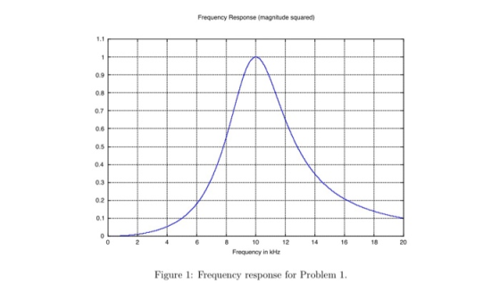
Frequency Response (magnitude squared 1.1 0.9 0.8 0.7 0.6 0.5 0.4 0.3 0.2 10 12 14 16 18 20 Frequency in kHz Figure 1: Frequency response for Problem 1
Homework Answers

Add Answer to:
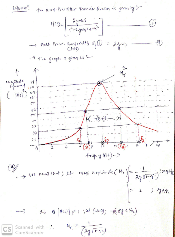
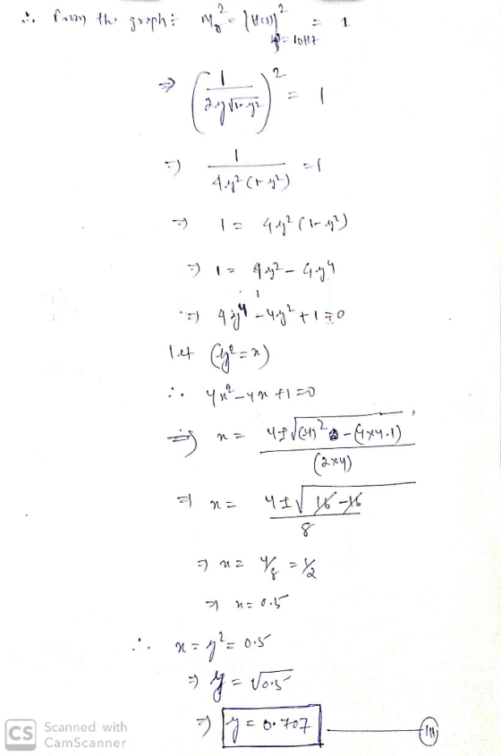
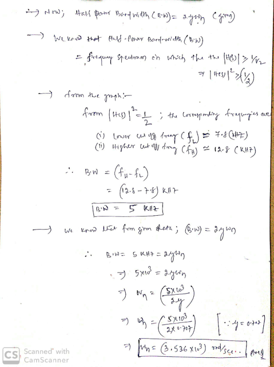
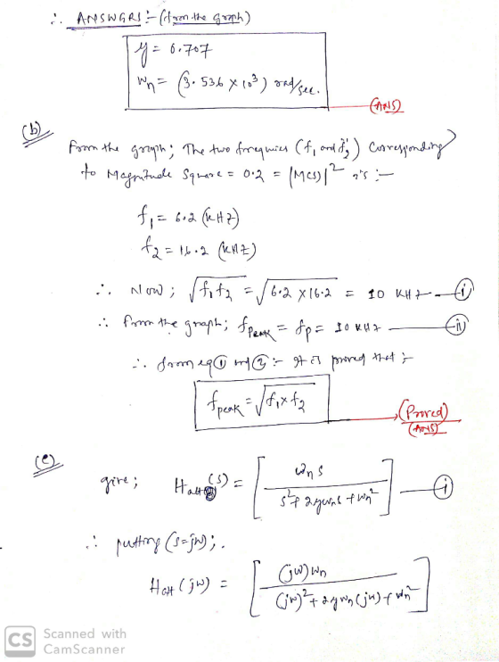
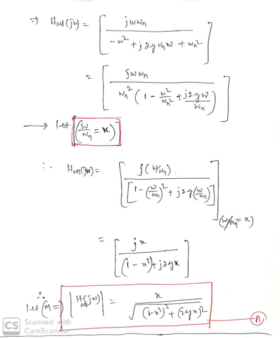
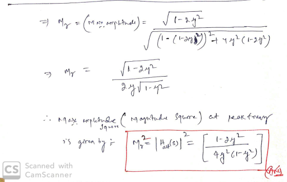
PROBLEM 8.1 Consider a bandpass filter specified by the system function 2Swns H (s) = Note that t...
Consider the following transfer function of a bandpass filter: 20 1,500 T(S) = 2 1,500 +...
 Consider the following transfer function of a bandpass filter: 20 1,500 T(S) = 2 1,500 + 1)(30.000 +1) a) Draw the Bode plot (magnitude and phase) of T(s). Label the slopes (dB/decade) b) Name the filter type. c) Determine the resonant frequency o d) Determine the gain in dB at the resonant frequency e) Determine bandwidth B, and the quality factor of the filter. Magnitude (dB) Phase (Deg)
3.2 Simple Bandpass Filter Design The L-point averaging filter is a lowpass filter. Its passband width...
 3.2 Simple Bandpass Filter Design The L-point averaging filter is a lowpass filter. Its passband width is controlled by L, being inversely proportional to L. In fact, you can use the GUI altidemo to view the frequency response for different averagers and measure the passband widths. It is also possible to create a filter whose passband is centered around some frequency other than zero. One simple way to do this is to define the impulse response of an L-point FIR...
1. Design a parallel RLC bandpass filter, derive the transfer function H(s). Compute the center frequency, Wo. Calculate the cutoff frequencies Wej and Wc2, the bandwidth ß, and quality factor, Q. Co...
 1. Design a parallel RLC bandpass filter, derive the transfer function H(s). Compute the center frequency, Wo. Calculate the cutoff frequencies Wej and Wc2, the bandwidth ß, and quality factor, Q. Compute values for R and L to yield a bandpass filter with a center frequency of 5kHz and a bandwidth of 200Hz, using a 10nF capacitor. (25 points)
1. Design a parallel RLC bandpass filter, derive the transfer function H(s). Compute the center frequency, Wo. Calculate the cutoff frequencies...
1. Design a parallel RLC bandpass filter, derive the transfer function H(s). Compute the center frequency, Wo. Calculate the cutoff frequencies Wej and Wc2, the bandwidth ß, and quality factor, Q. Compute values for R and L to yield a bandpass filter with a center frequency of 5kHz and a bandwidth of 200Hz, using a 10nF capacitor. (25 points)
1. Design a parallel RLC bandpass filter, derive the transfer function H(s). Compute the center frequency, Wo. Calculate the cutoff frequencies...
BPF Filter Bandpass Filter The following circuit acts as a C This filter has a center...
 BPF Filter Bandpass Filter The following circuit acts as a C This filter has a center (resonance) frequency at Hz. 27-VLC and a 3-dB bandwidth of BW = Hz. 2RC 3l f, and a passband for which the signal is This means that the filter has 0 dB gain at attenuated less than 3 dB centered approximately at f, from f,-BW2 to f.+BW/2 (this passband is not exactly centered at f, but its total width is BW) 3l8 Input Signal...
Design an active unity-gain bandpass filter with center frequency 750 Hz and bandwidtg 250 Hz and...
 Design an active unity-gain bandpass filter with
center frequency 750 Hz and bandwidtg 250 Hz and with 0.1 μF
capacitor, R1=6.4kΩ, R2=377Ω, and R3=12.7kΩ.
a)Discuss the circuit response with support of a Bode
magnitude plot.
b) Assume next that a load R_L is connected to the output of the
network at the terminal Vo(s). How does the frequency response of
the loaded configuration change?
c) Consider a broadband bandpass op amp filter with center
frequency 2.4 kHz and bandwidth 800...
Design an active unity-gain bandpass filter with
center frequency 750 Hz and bandwidtg 250 Hz and with 0.1 μF
capacitor, R1=6.4kΩ, R2=377Ω, and R3=12.7kΩ.
a)Discuss the circuit response with support of a Bode
magnitude plot.
b) Assume next that a load R_L is connected to the output of the
network at the terminal Vo(s). How does the frequency response of
the loaded configuration change?
c) Consider a broadband bandpass op amp filter with center
frequency 2.4 kHz and bandwidth 800...
(14%) 6. Consider an FM modulator with output )-100 cos(2(1000)r+(0) The modulator operates with fa = 8 and has the input message signal The modulator is followed by a bandpass filter with a...
 (14%) 6. Consider an FM modulator with output )-100 cos(2(1000)r+(0) The modulator operates with fa = 8 and has the input message signal The modulator is followed by a bandpass filter with a a bandwidth of 56HZ, as shown in the following figure. Determine the power ratio and the power at the fiter oput center frequency of 1000HZ and Bandpass filter PM Output Center 1000 Hz Bandwidth 56 Hz mt-5 cos 2(8)r modulator -1000 Hz (a) FM system 39.1 39.1365...
0.55 +0.5 102 S Problem 4.4 In Fig. 4.4, R=0.2 M2, C=25 pF and L=0.04 H....
 0.55 +0.5 102 S Problem 4.4 In Fig. 4.4, R=0.2 M2, C=25 pF and L=0.04 H. Show that the transfer function H(s) is: 1 (5) H(S)= (5) + +1 L102 107 (a) Plot the pole-zero diagram of H(s). (b) What filter is given by H(s)? Why? (e) Determine the resonant frequency 0o, the quality factor Q, the cut-off frequencies 01 and 02 and the bandwidth B. i (0) it) R Fig. 4.4
Please solve problem 4.5-2 ( a,b, and c) and be clear when you write by your hand.
 Please solve problem 4.5-2 ( a,b, and c) and be clear when you
write by your hand.
Problems Figure P.4.5-2 HI(f) ed 0.5 f, MHz 1.496 1.499 1.5 1.501 Figure P.4.5-3 Bandpass filter l us shoWn in Hz. Fig. P4.5-1. The carrier frequency is fe 10 kHz and the baseband signal bandwidth is 4k Find the corresponding transfer function of the equalizer filter Ho) shown in the receiver Fig. 4.21. Hint: Use Eq. (4.25). Figure P.4.5-1 H,(o) 0 9 10...
Please solve problem 4.5-2 ( a,b, and c) and be clear when you
write by your hand.
Problems Figure P.4.5-2 HI(f) ed 0.5 f, MHz 1.496 1.499 1.5 1.501 Figure P.4.5-3 Bandpass filter l us shoWn in Hz. Fig. P4.5-1. The carrier frequency is fe 10 kHz and the baseband signal bandwidth is 4k Find the corresponding transfer function of the equalizer filter Ho) shown in the receiver Fig. 4.21. Hint: Use Eq. (4.25). Figure P.4.5-1 H,(o) 0 9 10...
5) Consider the following second-order bandpass filter. As input voltage, apply V(t) 100Ω, C-4.7 μF. and L-10mH. sin(wt).R in Vout Fig 9: Second-order band-pass filter a) Determine the frequenc...
 5) Consider the following second-order bandpass filter. As input voltage, apply V(t) 100Ω, C-4.7 μF. and L-10mH. sin(wt).R in Vout Fig 9: Second-order band-pass filter a) Determine the frequency response function H(ju) Ve-ju) / Vm(ju) and sketch the magnitude and phase characteristics versus w by calaulation. Calculate the theoretical cutoff frequency of the filter Using PSpice AC analysis, plot magnitude lHju)l and phase ф characteristics of the filter, between 1 Hz-100 KHz b) c)
5) Consider the following second-order bandpass...
5) Consider the following second-order bandpass filter. As input voltage, apply V(t) 100Ω, C-4.7 μF. and L-10mH. sin(wt).R in Vout Fig 9: Second-order band-pass filter a) Determine the frequency response function H(ju) Ve-ju) / Vm(ju) and sketch the magnitude and phase characteristics versus w by calaulation. Calculate the theoretical cutoff frequency of the filter Using PSpice AC analysis, plot magnitude lHju)l and phase ф characteristics of the filter, between 1 Hz-100 KHz b) c)
5) Consider the following second-order bandpass...
b) Given a second order system with the following open loop transfer function where damping ratio,...
 b) Given a second order system with the following open loop transfer function where damping ratio, } = 0.707 and natural frequency, Wn= 2.5. wn? G(S) = S2 + 23wns +wn? i. Determine the steady state error to an appropriate input via a calculation method using the transfer function. Compare your answer with the steady state error from the exact frequency response for this system given in Figure Q4(b). (5 marks) ii. Evaluate the difference of the exact frequency response...
 Consider the following transfer function of a bandpass filter: 20 1,500 T(S) = 2 1,500 + 1)(30.000 +1) a) Draw the Bode plot (magnitude and phase) of T(s). Label the slopes (dB/decade) b) Name the filter type. c) Determine the resonant frequency o d) Determine the gain in dB at the resonant frequency e) Determine bandwidth B, and the quality factor of the filter. Magnitude (dB) Phase (Deg)
 3.2 Simple Bandpass Filter Design The L-point averaging filter is a lowpass filter. Its passband width is controlled by L, being inversely proportional to L. In fact, you can use the GUI altidemo to view the frequency response for different averagers and measure the passband widths. It is also possible to create a filter whose passband is centered around some frequency other than zero. One simple way to do this is to define the impulse response of an L-point FIR...
 1. Design a parallel RLC bandpass filter, derive the transfer function H(s). Compute the center frequency, Wo. Calculate the cutoff frequencies Wej and Wc2, the bandwidth ß, and quality factor, Q. Compute values for R and L to yield a bandpass filter with a center frequency of 5kHz and a bandwidth of 200Hz, using a 10nF capacitor. (25 points)
1. Design a parallel RLC bandpass filter, derive the transfer function H(s). Compute the center frequency, Wo. Calculate the cutoff frequencies...
1. Design a parallel RLC bandpass filter, derive the transfer function H(s). Compute the center frequency, Wo. Calculate the cutoff frequencies Wej and Wc2, the bandwidth ß, and quality factor, Q. Compute values for R and L to yield a bandpass filter with a center frequency of 5kHz and a bandwidth of 200Hz, using a 10nF capacitor. (25 points)
1. Design a parallel RLC bandpass filter, derive the transfer function H(s). Compute the center frequency, Wo. Calculate the cutoff frequencies...
 BPF Filter Bandpass Filter The following circuit acts as a C This filter has a center (resonance) frequency at Hz. 27-VLC and a 3-dB bandwidth of BW = Hz. 2RC 3l f, and a passband for which the signal is This means that the filter has 0 dB gain at attenuated less than 3 dB centered approximately at f, from f,-BW2 to f.+BW/2 (this passband is not exactly centered at f, but its total width is BW) 3l8 Input Signal...
 Design an active unity-gain bandpass filter with
center frequency 750 Hz and bandwidtg 250 Hz and with 0.1 μF
capacitor, R1=6.4kΩ, R2=377Ω, and R3=12.7kΩ.
a)Discuss the circuit response with support of a Bode
magnitude plot.
b) Assume next that a load R_L is connected to the output of the
network at the terminal Vo(s). How does the frequency response of
the loaded configuration change?
c) Consider a broadband bandpass op amp filter with center
frequency 2.4 kHz and bandwidth 800...
Design an active unity-gain bandpass filter with
center frequency 750 Hz and bandwidtg 250 Hz and with 0.1 μF
capacitor, R1=6.4kΩ, R2=377Ω, and R3=12.7kΩ.
a)Discuss the circuit response with support of a Bode
magnitude plot.
b) Assume next that a load R_L is connected to the output of the
network at the terminal Vo(s). How does the frequency response of
the loaded configuration change?
c) Consider a broadband bandpass op amp filter with center
frequency 2.4 kHz and bandwidth 800...
 (14%) 6. Consider an FM modulator with output )-100 cos(2(1000)r+(0) The modulator operates with fa = 8 and has the input message signal The modulator is followed by a bandpass filter with a a bandwidth of 56HZ, as shown in the following figure. Determine the power ratio and the power at the fiter oput center frequency of 1000HZ and Bandpass filter PM Output Center 1000 Hz Bandwidth 56 Hz mt-5 cos 2(8)r modulator -1000 Hz (a) FM system 39.1 39.1365...
 0.55 +0.5 102 S Problem 4.4 In Fig. 4.4, R=0.2 M2, C=25 pF and L=0.04 H. Show that the transfer function H(s) is: 1 (5) H(S)= (5) + +1 L102 107 (a) Plot the pole-zero diagram of H(s). (b) What filter is given by H(s)? Why? (e) Determine the resonant frequency 0o, the quality factor Q, the cut-off frequencies 01 and 02 and the bandwidth B. i (0) it) R Fig. 4.4
 Please solve problem 4.5-2 ( a,b, and c) and be clear when you
write by your hand.
Problems Figure P.4.5-2 HI(f) ed 0.5 f, MHz 1.496 1.499 1.5 1.501 Figure P.4.5-3 Bandpass filter l us shoWn in Hz. Fig. P4.5-1. The carrier frequency is fe 10 kHz and the baseband signal bandwidth is 4k Find the corresponding transfer function of the equalizer filter Ho) shown in the receiver Fig. 4.21. Hint: Use Eq. (4.25). Figure P.4.5-1 H,(o) 0 9 10...
Please solve problem 4.5-2 ( a,b, and c) and be clear when you
write by your hand.
Problems Figure P.4.5-2 HI(f) ed 0.5 f, MHz 1.496 1.499 1.5 1.501 Figure P.4.5-3 Bandpass filter l us shoWn in Hz. Fig. P4.5-1. The carrier frequency is fe 10 kHz and the baseband signal bandwidth is 4k Find the corresponding transfer function of the equalizer filter Ho) shown in the receiver Fig. 4.21. Hint: Use Eq. (4.25). Figure P.4.5-1 H,(o) 0 9 10...
 5) Consider the following second-order bandpass filter. As input voltage, apply V(t) 100Ω, C-4.7 μF. and L-10mH. sin(wt).R in Vout Fig 9: Second-order band-pass filter a) Determine the frequency response function H(ju) Ve-ju) / Vm(ju) and sketch the magnitude and phase characteristics versus w by calaulation. Calculate the theoretical cutoff frequency of the filter Using PSpice AC analysis, plot magnitude lHju)l and phase ф characteristics of the filter, between 1 Hz-100 KHz b) c)
5) Consider the following second-order bandpass...
5) Consider the following second-order bandpass filter. As input voltage, apply V(t) 100Ω, C-4.7 μF. and L-10mH. sin(wt).R in Vout Fig 9: Second-order band-pass filter a) Determine the frequency response function H(ju) Ve-ju) / Vm(ju) and sketch the magnitude and phase characteristics versus w by calaulation. Calculate the theoretical cutoff frequency of the filter Using PSpice AC analysis, plot magnitude lHju)l and phase ф characteristics of the filter, between 1 Hz-100 KHz b) c)
5) Consider the following second-order bandpass...
 b) Given a second order system with the following open loop transfer function where damping ratio, } = 0.707 and natural frequency, Wn= 2.5. wn? G(S) = S2 + 23wns +wn? i. Determine the steady state error to an appropriate input via a calculation method using the transfer function. Compare your answer with the steady state error from the exact frequency response for this system given in Figure Q4(b). (5 marks) ii. Evaluate the difference of the exact frequency response...
Most questions answered within 3 hours.
-
Write the ionic equations for the first stage of salts
hydrolysis.
Anion, Cation?
Na2S
NiSO4
K2SO4...
asked 1 hour ago -
suppose there is a normally distributed population with a mean of
250 and a standard deviation...
asked 1 hour ago -
Question Three
Suppose you as project manager are using the Waterfall
development methodology on a large...
asked 2 hours ago -
Which statement is not true about welfare in Canada?
A.Benefits typically vary based on one's ability...
asked 3 hours ago -
Please help me with FLOWCHART and UML diagram for class,
thank you!
#include <iostream>
#include <fstream>...
asked 4 hours ago -
3. Describe the “logic circuit” of the Lac operon. Which
proteins are bound or not to...
asked 4 hours ago -
Ayesha’s adjusted gross income is $60,000 in 2019. She donated a
piece of artwork with a...
asked 4 hours ago -
For Dijkstra’s shortest path algorithm:
a. Give the Big-O time for Dijkstra’s shortest path algorithm
and...
asked 4 hours ago -
Phosphorus violates the 'octet rule' in biological molecules,
forming more covalent bonds than expected based on...
asked 4 hours ago -
A 1.3 eV electron has a 10-4 probability of tunneling
through a 2.4 eV potential barrier....
asked 4 hours ago -
What is the one ingredient that is common to being successful
with all stakeholders?
profit
trust...
asked 4 hours ago -
Write an assembly language 32 bit program that reads in lines of
text by a .txt...
asked 4 hours ago