
Homework Answers
Given

a)Loading diagram

Taking moment Balance about A

Taking force balance

b)
Shear force diagram

c)

At mid-span shear force is zero so the bending moment is maximum at mid-span

d)
The bending moment at A and B is zero and the maximum bending moment at mid-span.
Since the second derivative of the bending moment is constant the bending diagram should be a parabola.
Bending moment diagram

Since bending moment diagram have positive bending moment throughout
Therefore the beam will be sagging
e)
Maximum bending moment

Bending stress equation

At mid-span, we will get maximum bending stress


The allowable loading for bottom fiber is small so it is the safest loading

If we chose the allowable loading for top fiber then the bottom fiber will fail.
So the safest maximum loading is the 6.924 kN/m
Add Answer to:
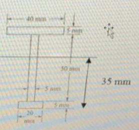
The simply-supported beam having I-beam cross-section as shown in figure is to carry a uniformly distributed...
Simply supported beam is loaded as shown in figure. (a) Compute support reactions. (3) (b) Draw...
 Simply supported beam is loaded as shown in figure. (a) Compute support reactions. (3) (b) Draw Shear Force Diagram (SFD) to the scale. (c) Locate the point where shear force is zero. Do not use properties of similar triangles. (3) (d) Compute bending moment at all important points including point where shear force is zero. (4) (e) Draw Bending Moment Diagram (BMD) to the scale. (4) (1) Show deflected shape of the beam. Indicate which part is sagging and which...
The beam having a cross-section as shown is subjected to the distributed load w (1) Calculate...
 The beam having a cross-section as shown is subjected to the distributed load w (1) Calculate the moment of inertia, I (2) If the allowable maximum normal stress ơmax-20 MPa, determine the largest distributed load 5. w. (3) If w 1.5 kN/m, determine the maximum bending stress in the beam. Sketch the stress distribution acting over the cross-section. 100 mm 50mm 120 mm 3 m50 mm 3 m
Question 1: Consider the beam below. Please use the table below to determine the appropriate valu...
 Question 1: Consider the beam below. Please use the table below to determine the appropriate values for your question. The effects of self-weight are negligible compared to effects of the applied loading. Draw the bending moment diagram (BMD) and shear force diagram (SFD), clearly indicating the values of V & Mat A, B, C, & D Also show the location(s) and value(s) of maximum sagging and/or hogging moment. Include your working. L2 L3 Group 2A Li (mm) w (kN/m)P (kN)...
A simply supported beam as shown in the figure. The beam section is W18x211. The beam...
 A simply supported beam as shown in the figure. The beam section is W18x211. The beam must support its own weight and must carry the following loading: Super-imposed distributed dead load = 0.25 kip/ft Distributed live load = 1 kip/ft Concentrated dead load = 12 kip The beam span L = 26 ft and the distance of the concentrated load from the right support a=6 ft. Consider analy- sis of beam subjected to load combination 1.2 dead + 1.6 live....
The simply supported beam, with a U cross section, is subjected to a uniformly distributed force...
 The simply supported beam, with a U cross section, is subjected to a uniformly distributed force of 8 kN/m and a concentrated load of 12 kN as shown. (a) Determine the reaction at supports A and B, (b) sketch the shear diagram and the moment diagram, (c) determine the location of the neutral axis of the cross section and calculate its area moment of inertia about the neutral axis, and (d) determine absolute maximum bending stress and (e) absolute maximum...
Figure Q3 shows a simply supported beam carrying a point load. The beam hasa rectangular hollow...
 Figure Q3 shows a simply supported beam carrying a point load. The beam hasa rectangular hollow steel section as shown in Figure Q3. a. Calculate the second moment of area of the section about the horizontal (10 marks) centroidal axis. Calculate the maximum allowable value of the point load Wif the elastic bending (15 marks) b. stress in the beam is to be limited to 250 MPa. c. Calculate the maximum shear stress at q-q in the beam when the...
1. Consider a simply-supported beam with a triangular cross section (Fig. 1). If the allowable bending...
 1. Consider a simply-supported beam with a triangular cross section (Fig. 1). If the allowable bending stress is oallow = 150 MPa, determine the maximum intensity w of the uniformly distributed load. Draw the corresponding shear force and bending moment diagrams В 6m 300 mm 1bh 150 mm Triangular area (a) (b) Figure 1 10 points =15°C, the gap between 2. Fig. 2 shows two cylindrical rod segments fixed to the rigid walls. At To them is 0.25 mm. Each...
The beam has the triangular cross section shown. The allowable stress in bending is 150 MPa....
 The beam has the triangular cross section shown. The allowable stress in bending is 150 MPa. Determine the largest allowed uniform distributed load w. 6 m 300 mm 150 mm
P8.008 The dimensions of the double-box beam cross section shown in the figure are b =...
 P8.008 The dimensions of the double-box beam cross section shown in the figure are b = 190 mm, d = 65 mm, and t = 3 mm. If the maximum allowable bending stress is 19 MPa, determine the maximum internal bending moment Mz magnitude that can be applied to the beam. Answer: Mz = N-m
Question 3 For the simply supported steel beam with cross section and loading shown (see Figure...
 Question 3 For the simply supported steel beam with cross section and loading shown (see Figure 3a), knowing that uniformly distributed load w=60 kN/m, Young modulus E = 200 GPa, and yield stress Cyield=200 MPa (in both tension and compression). ул 15 mm w=60 kN/m ... 1 B A 15 mm + 300 mm IC - i 2.5m 1 1 15 mm 7.5m 1 150 mm Figure 3a (a) Check if: the beam is safe with respect to yielding (using...
 Simply supported beam is loaded as shown in figure. (a) Compute support reactions. (3) (b) Draw Shear Force Diagram (SFD) to the scale. (c) Locate the point where shear force is zero. Do not use properties of similar triangles. (3) (d) Compute bending moment at all important points including point where shear force is zero. (4) (e) Draw Bending Moment Diagram (BMD) to the scale. (4) (1) Show deflected shape of the beam. Indicate which part is sagging and which...
 The beam having a cross-section as shown is subjected to the distributed load w (1) Calculate the moment of inertia, I (2) If the allowable maximum normal stress ơmax-20 MPa, determine the largest distributed load 5. w. (3) If w 1.5 kN/m, determine the maximum bending stress in the beam. Sketch the stress distribution acting over the cross-section. 100 mm 50mm 120 mm 3 m50 mm 3 m
 Question 1: Consider the beam below. Please use the table below to determine the appropriate values for your question. The effects of self-weight are negligible compared to effects of the applied loading. Draw the bending moment diagram (BMD) and shear force diagram (SFD), clearly indicating the values of V & Mat A, B, C, & D Also show the location(s) and value(s) of maximum sagging and/or hogging moment. Include your working. L2 L3 Group 2A Li (mm) w (kN/m)P (kN)...
 A simply supported beam as shown in the figure. The beam section is W18x211. The beam must support its own weight and must carry the following loading: Super-imposed distributed dead load = 0.25 kip/ft Distributed live load = 1 kip/ft Concentrated dead load = 12 kip The beam span L = 26 ft and the distance of the concentrated load from the right support a=6 ft. Consider analy- sis of beam subjected to load combination 1.2 dead + 1.6 live....
 Figure Q3 shows a simply supported beam carrying a point load. The beam hasa rectangular hollow steel section as shown in Figure Q3. a. Calculate the second moment of area of the section about the horizontal (10 marks) centroidal axis. Calculate the maximum allowable value of the point load Wif the elastic bending (15 marks) b. stress in the beam is to be limited to 250 MPa. c. Calculate the maximum shear stress at q-q in the beam when the...
 1. Consider a simply-supported beam with a triangular cross section (Fig. 1). If the allowable bending stress is oallow = 150 MPa, determine the maximum intensity w of the uniformly distributed load. Draw the corresponding shear force and bending moment diagrams В 6m 300 mm 1bh 150 mm Triangular area (a) (b) Figure 1 10 points =15°C, the gap between 2. Fig. 2 shows two cylindrical rod segments fixed to the rigid walls. At To them is 0.25 mm. Each...
 The beam has the triangular cross section shown. The allowable stress in bending is 150 MPa. Determine the largest allowed uniform distributed load w. 6 m 300 mm 150 mm
 P8.008 The dimensions of the double-box beam cross section shown in the figure are b = 190 mm, d = 65 mm, and t = 3 mm. If the maximum allowable bending stress is 19 MPa, determine the maximum internal bending moment Mz magnitude that can be applied to the beam. Answer: Mz = N-m
 Question 3 For the simply supported steel beam with cross section and loading shown (see Figure 3a), knowing that uniformly distributed load w=60 kN/m, Young modulus E = 200 GPa, and yield stress Cyield=200 MPa (in both tension and compression). ул 15 mm w=60 kN/m ... 1 B A 15 mm + 300 mm IC - i 2.5m 1 1 15 mm 7.5m 1 150 mm Figure 3a (a) Check if: the beam is safe with respect to yielding (using...
Most questions answered within 3 hours.
-
Calculate the pH of a 5.7 M solution of aniline (C6H5NH2; Kb =
3.8 x 10^-10)
asked 1 hour ago -
LSL R3, R3, R12
Memory
Address
Orig.
Data
Updated
Data
Register
Orig.
Data
Updated
Data
0x84F0...
asked 1 hour ago -
Air at 100 kPa and density of 1.2 kg/m3 flows upward through a
5-cm diameter inclined...
asked 1 hour ago -
Define the following concepts in your own words: (a) stiffness,
(b) strength, (c) strain,
(d) ductility,...
asked 2 hours ago -
In C++
In this homework, you will be tasked with creating functions to
manipulate strings that...
asked 3 hours ago -
An isolated colony represents a pure culture. one rare occasions
, however , a colony can...
asked 3 hours ago -
*****DO NOT ANSWER THIS QUESTION IF YOU DON'T
KNOW*******Rights and Duties of Auditors; Minimum 4000
words...
asked 4 hours ago -
The probability that Janie is wearing sunglasses is 1/4. The
probability that she is wearing sunglasses...
asked 4 hours ago -
Do you believe social media is more of a help or a hindrance in
controlling crises...
asked 5 hours ago -
Two long, parallel wires separated by 2.85 cm carry currents in
opposite directions. The current in...
asked 4 hours ago -
Question # 1. Develop a list of rehabilitation journals
that publish articles concerning career counseling for...
asked 5 hours ago -
Bryant Company has a factory machine with a book value of
$85,100 and a remaining useful...
asked 5 hours ago