


Homework Answers


Add Answer to:
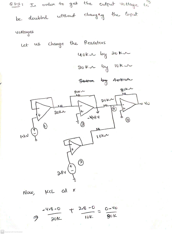
Question 3 (Marks: 14) Regarding the following Op-Amp circuit in figure 3: 80 kΩ 80 kΩ...
Good morning, I need help with the following, they all relate to OP Amps. Thanks in advance. 2 value 10.00 points Problem 05.010 An op amp voltage divider Find the voltage gain vo/vs of the circ...
 Good morning, I need help with the following, they all relate to
OP Amps. Thanks in advance.
2 value 10.00 points Problem 05.010 An op amp voltage divider Find the voltage gain vo/vs of the circuit given below, where R1-18 kΩ and R2-14 k 2. 20 kΩ R1 1% R2 The voltage gain vo/vs of the circuit is Hints Referene eBook & Resources Hint#1 Check my work 3. 1000 points value Problem 05.025-Voltage follower Calculate the output voltage vo in...
Good morning, I need help with the following, they all relate to
OP Amps. Thanks in advance.
2 value 10.00 points Problem 05.010 An op amp voltage divider Find the voltage gain vo/vs of the circuit given below, where R1-18 kΩ and R2-14 k 2. 20 kΩ R1 1% R2 The voltage gain vo/vs of the circuit is Hints Referene eBook & Resources Hint#1 Check my work 3. 1000 points value Problem 05.025-Voltage follower Calculate the output voltage vo in...
8.) In the OP amp circuit shown in Figure 8 , determine the value of resistor...
 8.) In the OP amp circuit shown in Figure 8 , determine the
value of resistor R2 needed to establish an input trip point
voltage of 6.75 Volts ( i.e. when input signal voltage V in exceeds
6.75 V the OP amp’s output voltage changes state ) . ( 60 pts )
R2 = _______________
If the OP AMP in Figure 8 was biased by DC voltages of + / - 15
Volts , and the value of resistor R2...
8.) In the OP amp circuit shown in Figure 8 , determine the
value of resistor R2 needed to establish an input trip point
voltage of 6.75 Volts ( i.e. when input signal voltage V in exceeds
6.75 V the OP amp’s output voltage changes state ) . ( 60 pts )
R2 = _______________
If the OP AMP in Figure 8 was biased by DC voltages of + / - 15
Volts , and the value of resistor R2...
The op amp in the circuit in (Figure 1) is ideal. Suppose R-16 kΩ Part A...
 The op amp in the circuit in (Figure 1) is ideal. Suppose R-16 kΩ Part A What op amp circuit configuration is this? O This circuit is an example of the inverting amplifier o This circuit is an example of the non-inverting amplifier Submit Request Answer ▼ Part B Find vo in terms of vs Express your answer in terms of vs 07 Figure 1 of 1 > Submit Request Answer Part C 56 kΩ Find the minimum value of...
Problem 7 (CLO 3, 4, 11 - Ideal Op-Amps, Design): We will now design an Op-Amp...
 Problem 7 (CLO 3, 4, 11 - Ideal Op-Amps, Design): We will now design an Op-Amp circuit to perform the function where v1 - input voltage 1, input voltage 2, = input voltage 3, Vo = output voltage. It may be helpful to consult your recitation 6 (week 7) results as well as Table 4-3 for this problem. 7.a: Select an Op-Amp configuration for your design. Sketch the Op-Amp configuration with symbolic resistors (Rf, Ri, R2, etc) indicated. Do not...
Assuming an ideal op-amp (1)find the 3dB frequency of the circuit, if R1=1.5 KΩ, R2=13.2 KΩ,...
 Assuming an ideal op-amp (1)find
the 3dB frequency of the circuit, if R1=1.5 KΩ, R2=13.2
KΩ, R3=20 KΩ, and C=5 nF
2)Consider the above circuit with the component
values: R1=13.2 KΩ, R2= 795.77 Ω, R3=20
KΩ, and C=100 nF. Find the angle of the transfer
function in degrees at 2KHz .
- C R2 R1 + Vi(jw) Vo R3 H HI-
Assuming an ideal op-amp (1)find
the 3dB frequency of the circuit, if R1=1.5 KΩ, R2=13.2
KΩ, R3=20 KΩ, and C=5 nF
2)Consider the above circuit with the component
values: R1=13.2 KΩ, R2= 795.77 Ω, R3=20
KΩ, and C=100 nF. Find the angle of the transfer
function in degrees at 2KHz .
- C R2 R1 + Vi(jw) Vo R3 H HI-
1)What is the output voltage V0 if op-amp is ideal? R1= 2 KΩ, R2=8 KΩ, R3=3.2...
 1)What is the output
voltage V0 if op-amp is ideal?
R1= 2 KΩ, R2=8 KΩ, R3=3.2 KΩ, R4=6 KΩ, R5=19
KΩ, R6=4.6 KΩ, RL=9.6 KΩ, V1=1V, I2=0.5 mA and V3=2.5 V.
2) for the same circuit, R1= 2 KΩ R2=8
KΩ, R3=3.6 KΩ, R4=6 KΩ, R5=16.9 KΩ, R6=15 KΩ, RL=10 KΩ, V1=1V,
I2=0.5mA and V3=2V. What is the input impedance as
seen by source V3?
+ | R1 ہی ہے۔ ۸۸۸ ة -(1+ R5 | + ابرها -
1)What is the output
voltage V0 if op-amp is ideal?
R1= 2 KΩ, R2=8 KΩ, R3=3.2 KΩ, R4=6 KΩ, R5=19
KΩ, R6=4.6 KΩ, RL=9.6 KΩ, V1=1V, I2=0.5 mA and V3=2.5 V.
2) for the same circuit, R1= 2 KΩ R2=8
KΩ, R3=3.6 KΩ, R4=6 KΩ, R5=16.9 KΩ, R6=15 KΩ, RL=10 KΩ, V1=1V,
I2=0.5mA and V3=2V. What is the input impedance as
seen by source V3?
+ | R1 ہی ہے۔ ۸۸۸ ة -(1+ R5 | + ابرها -
In the given op amp circuit, R1 = 3 R and R2 = 4 R. Determine...
 In the given op amp circuit, R1 = 3
R and R2 = 4 R. Determine the
voltage gain vo/vs. Assume
that R = 10 kΩ.
The voltage gain vo/vs
is
In the given op amp circuit, R1 = 3 R and R2 = 4 R. Determine the voltage gain vol Vs. Assume that R = 10 k.. R R WBA R w R w + 0 + TO The voltage gain Vo/Vs is
In the given op amp circuit, R1 = 3
R and R2 = 4 R. Determine the
voltage gain vo/vs. Assume
that R = 10 kΩ.
The voltage gain vo/vs
is
In the given op amp circuit, R1 = 3 R and R2 = 4 R. Determine the voltage gain vol Vs. Assume that R = 10 k.. R R WBA R w R w + 0 + TO The voltage gain Vo/Vs is
Part D? The op amp in the circuit in (Figure 1) is ideal. Suppose R =...
 Part D?
The op amp in the circuit in (Figure 1) is ideal. Suppose R = 35 kΩ. Figure K 1 of 1 Σ 60 kΩ 30 ΚΩ 8 ΚΩ 15 V W X40 ΚΩ + 240 mV -15V Part A Calculate ia Express your answer to three significant figures and include the appropriate units. ia = 3.00x10⁻⁵ A Submit Previous Answers Correct Part B Calculate va Express your answer to three significant figures and include the appropriate units. Va...
Part D?
The op amp in the circuit in (Figure 1) is ideal. Suppose R = 35 kΩ. Figure K 1 of 1 Σ 60 kΩ 30 ΚΩ 8 ΚΩ 15 V W X40 ΚΩ + 240 mV -15V Part A Calculate ia Express your answer to three significant figures and include the appropriate units. ia = 3.00x10⁻⁵ A Submit Previous Answers Correct Part B Calculate va Express your answer to three significant figures and include the appropriate units. Va...
2. Design a non-inverting op-amp circuit with two resistors under the following conditions: a. The gain of the ampl...
 2. Design a non-inverting op-amp circuit with two resistors under the following conditions: a. The gain of the amplifier must be +10 b. The input range is ± 2V c. The total power consumed by the resistors must be less than 100 mW Show all the calculations required to design the amplifier circuit with the shown specifications.in details Use MULTISIM to create the op-amp circuit and print a fully labelled diagram of the circuits with the voltmeters displays showing both...
Find V. in the circuit in the figure below using superposition. =3 mA 7 kΩ Ο...
 Find V. in the circuit in the figure below using superposition. =3 mA 7 kΩ Ο 4 kg 7 kΩ Ta = 2V I h = 8V 4 ΚΩ 6 kΩ Ι ο Vo with only V, turned on Vo with only V6 turned on 75.6 V with only I, on = V =
 Good morning, I need help with the following, they all relate to
OP Amps. Thanks in advance.
2 value 10.00 points Problem 05.010 An op amp voltage divider Find the voltage gain vo/vs of the circuit given below, where R1-18 kΩ and R2-14 k 2. 20 kΩ R1 1% R2 The voltage gain vo/vs of the circuit is Hints Referene eBook & Resources Hint#1 Check my work 3. 1000 points value Problem 05.025-Voltage follower Calculate the output voltage vo in...
Good morning, I need help with the following, they all relate to
OP Amps. Thanks in advance.
2 value 10.00 points Problem 05.010 An op amp voltage divider Find the voltage gain vo/vs of the circuit given below, where R1-18 kΩ and R2-14 k 2. 20 kΩ R1 1% R2 The voltage gain vo/vs of the circuit is Hints Referene eBook & Resources Hint#1 Check my work 3. 1000 points value Problem 05.025-Voltage follower Calculate the output voltage vo in...
 8.) In the OP amp circuit shown in Figure 8 , determine the
value of resistor R2 needed to establish an input trip point
voltage of 6.75 Volts ( i.e. when input signal voltage V in exceeds
6.75 V the OP amp’s output voltage changes state ) . ( 60 pts )
R2 = _______________
If the OP AMP in Figure 8 was biased by DC voltages of + / - 15
Volts , and the value of resistor R2...
8.) In the OP amp circuit shown in Figure 8 , determine the
value of resistor R2 needed to establish an input trip point
voltage of 6.75 Volts ( i.e. when input signal voltage V in exceeds
6.75 V the OP amp’s output voltage changes state ) . ( 60 pts )
R2 = _______________
If the OP AMP in Figure 8 was biased by DC voltages of + / - 15
Volts , and the value of resistor R2...
 The op amp in the circuit in (Figure 1) is ideal. Suppose R-16 kΩ Part A What op amp circuit configuration is this? O This circuit is an example of the inverting amplifier o This circuit is an example of the non-inverting amplifier Submit Request Answer ▼ Part B Find vo in terms of vs Express your answer in terms of vs 07 Figure 1 of 1 > Submit Request Answer Part C 56 kΩ Find the minimum value of...
 Problem 7 (CLO 3, 4, 11 - Ideal Op-Amps, Design): We will now design an Op-Amp circuit to perform the function where v1 - input voltage 1, input voltage 2, = input voltage 3, Vo = output voltage. It may be helpful to consult your recitation 6 (week 7) results as well as Table 4-3 for this problem. 7.a: Select an Op-Amp configuration for your design. Sketch the Op-Amp configuration with symbolic resistors (Rf, Ri, R2, etc) indicated. Do not...
 Assuming an ideal op-amp (1)find
the 3dB frequency of the circuit, if R1=1.5 KΩ, R2=13.2
KΩ, R3=20 KΩ, and C=5 nF
2)Consider the above circuit with the component
values: R1=13.2 KΩ, R2= 795.77 Ω, R3=20
KΩ, and C=100 nF. Find the angle of the transfer
function in degrees at 2KHz .
- C R2 R1 + Vi(jw) Vo R3 H HI-
Assuming an ideal op-amp (1)find
the 3dB frequency of the circuit, if R1=1.5 KΩ, R2=13.2
KΩ, R3=20 KΩ, and C=5 nF
2)Consider the above circuit with the component
values: R1=13.2 KΩ, R2= 795.77 Ω, R3=20
KΩ, and C=100 nF. Find the angle of the transfer
function in degrees at 2KHz .
- C R2 R1 + Vi(jw) Vo R3 H HI-
 1)What is the output
voltage V0 if op-amp is ideal?
R1= 2 KΩ, R2=8 KΩ, R3=3.2 KΩ, R4=6 KΩ, R5=19
KΩ, R6=4.6 KΩ, RL=9.6 KΩ, V1=1V, I2=0.5 mA and V3=2.5 V.
2) for the same circuit, R1= 2 KΩ R2=8
KΩ, R3=3.6 KΩ, R4=6 KΩ, R5=16.9 KΩ, R6=15 KΩ, RL=10 KΩ, V1=1V,
I2=0.5mA and V3=2V. What is the input impedance as
seen by source V3?
+ | R1 ہی ہے۔ ۸۸۸ ة -(1+ R5 | + ابرها -
1)What is the output
voltage V0 if op-amp is ideal?
R1= 2 KΩ, R2=8 KΩ, R3=3.2 KΩ, R4=6 KΩ, R5=19
KΩ, R6=4.6 KΩ, RL=9.6 KΩ, V1=1V, I2=0.5 mA and V3=2.5 V.
2) for the same circuit, R1= 2 KΩ R2=8
KΩ, R3=3.6 KΩ, R4=6 KΩ, R5=16.9 KΩ, R6=15 KΩ, RL=10 KΩ, V1=1V,
I2=0.5mA and V3=2V. What is the input impedance as
seen by source V3?
+ | R1 ہی ہے۔ ۸۸۸ ة -(1+ R5 | + ابرها -
 In the given op amp circuit, R1 = 3
R and R2 = 4 R. Determine the
voltage gain vo/vs. Assume
that R = 10 kΩ.
The voltage gain vo/vs
is
In the given op amp circuit, R1 = 3 R and R2 = 4 R. Determine the voltage gain vol Vs. Assume that R = 10 k.. R R WBA R w R w + 0 + TO The voltage gain Vo/Vs is
In the given op amp circuit, R1 = 3
R and R2 = 4 R. Determine the
voltage gain vo/vs. Assume
that R = 10 kΩ.
The voltage gain vo/vs
is
In the given op amp circuit, R1 = 3 R and R2 = 4 R. Determine the voltage gain vol Vs. Assume that R = 10 k.. R R WBA R w R w + 0 + TO The voltage gain Vo/Vs is
 Part D?
The op amp in the circuit in (Figure 1) is ideal. Suppose R = 35 kΩ. Figure K 1 of 1 Σ 60 kΩ 30 ΚΩ 8 ΚΩ 15 V W X40 ΚΩ + 240 mV -15V Part A Calculate ia Express your answer to three significant figures and include the appropriate units. ia = 3.00x10⁻⁵ A Submit Previous Answers Correct Part B Calculate va Express your answer to three significant figures and include the appropriate units. Va...
Part D?
The op amp in the circuit in (Figure 1) is ideal. Suppose R = 35 kΩ. Figure K 1 of 1 Σ 60 kΩ 30 ΚΩ 8 ΚΩ 15 V W X40 ΚΩ + 240 mV -15V Part A Calculate ia Express your answer to three significant figures and include the appropriate units. ia = 3.00x10⁻⁵ A Submit Previous Answers Correct Part B Calculate va Express your answer to three significant figures and include the appropriate units. Va...
 2. Design a non-inverting op-amp circuit with two resistors under the following conditions: a. The gain of the amplifier must be +10 b. The input range is ± 2V c. The total power consumed by the resistors must be less than 100 mW Show all the calculations required to design the amplifier circuit with the shown specifications.in details Use MULTISIM to create the op-amp circuit and print a fully labelled diagram of the circuits with the voltmeters displays showing both...
 Find V. in the circuit in the figure below using superposition. =3 mA 7 kΩ Ο 4 kg 7 kΩ Ta = 2V I h = 8V 4 ΚΩ 6 kΩ Ι ο Vo with only V, turned on Vo with only V6 turned on 75.6 V with only I, on = V =
Most questions answered within 3 hours.
-
The Baily Corporation has developed a specialized software
program that improves inventory control capability. The following...
asked 46 seconds from now -
Problem 5-4A (Part Level Submission) Wolford Department Store is
located in midtown Metropolis. During the past...
asked 39 seconds from now -
Preparation of Benzoic Acid using a Grignard Reagent URGENT
1. During your Grignard formation, a small...
asked 22 minutes ago -
A uniform magnetic field is perpendicular to the plane of a wire
loop. If the loop...
asked 21 minutes ago -
At the peak of your career, your were earning $120,000 and
holding a top level position....
asked 24 minutes ago -
. A permanent magnet is dropped south-end-down through a horizontal
circular coil with a radius of...
asked 26 minutes ago -
Bernie's Beverages purchased some fixed assets classified as
5-year property for MACRS. The assets cost $28,000....
asked 40 minutes ago -
How many ATPs are produced from the catabolism of a 10-C
molecule of fatty acid under...
asked 45 minutes ago -
Before practicing a routine on the rings, a 64.8 kg gymnast
hangs motionless, with one hand...
asked 46 minutes ago -
If the K b of a weak base is 6.3 × 10 − 6 , what...
asked 53 minutes ago -
Which of the following is the minimum amount of moles of NaOH
that must be added...
asked 56 minutes ago -
Stories about organizational ________ provide important clues
about cultural values and norms.
a. myths
b. heroes...
asked 58 minutes ago