For the planar mechanism of figure below, link 4 servers as slider support which is free to rotate about the z axis, but has point D kept stationary. Link 3 is a rigid member continuous over the rotational joint B. The lengths of the links 2 and 5 are respectively 3 cm and 7 cm, and the distance AB is 6 cm. The angles of the links 2, 3, and 5 with the positive horizontal are denoted as θ2 , θ3 and θ5 , respectively. At the instant of consideration these angles θ2 , θ3 and θ5 are respectively 100o , 331.2o and 70.1o , while the distance AD is 10 cm. For the constant CCW angular speed of 2 rad/s of the link 2, determine:
(b) The velocity of the slider C,

Homework Answers


Add Answer to:
For the planar mechanism of figure below, link 4 servers as
slider support which is free...
Question 1 In the mechanism of figure Q1 crank O2A rotates at 70 revim rotational speed. Slider B slides on sliding...
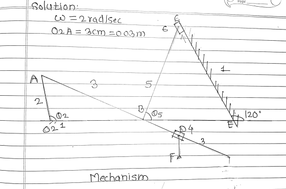
 Question 1 In the mechanism of figure Q1 crank O2A rotates at 70 revim rotational speed. Slider B slides on sliding link AC. T are as follows: O2A 6,0 cm, CD 10 cm, AB 2 cm, AC 8 cm, OsD 4 cm and O Angle θ2-1100 and θ5-100. Rotation) speed for 05 D:looney/ml Construct a velocity diagram for this position and t in clockwise about O2 at a constant he dimensions of the links of the mechanism [101 hen find...
2 The figure shows a mechanism consisting of a slider, attached to link 3 at B through a revolute...
 2 The figure shows a mechanism consisting of a slider, attached to link 3 at B through a revolute joint. Link 3 is attached to link 2 through a revolute joint at A. Link 2 is attached to the inertial frame through a revolute joint at O. Link 2 is 200 mm long and link 3 is 300 mm long. B is constrained to move in a slot angled at 40° to the horizontal. Initially, B is horizontally in line...
The planar four-bar mechanism shown below has a driving crank O1A that turns about O1 at...
 The planar four-bar mechanism shown below has a driving crank
O1A that turns about O1 at a constant rate of
(theta- dot) θ. = 10 rad/s CCW. The links O1A
and O2B are balanced and have a mass moments of inertia
about their center of mass of Iz = 0.02 kgm2 . The link
ABC has a center of mass located at point G, has a mass of m = 2
kg, and has a mass moment of inertia of...
The planar four-bar mechanism shown below has a driving crank
O1A that turns about O1 at a constant rate of
(theta- dot) θ. = 10 rad/s CCW. The links O1A
and O2B are balanced and have a mass moments of inertia
about their center of mass of Iz = 0.02 kgm2 . The link
ABC has a center of mass located at point G, has a mass of m = 2
kg, and has a mass moment of inertia of...
 Question 1 In the mechanism of figure Q1 crank O2A rotates at 70 revim rotational speed. Slider B slides on sliding link AC. T are as follows: O2A 6,0 cm, CD 10 cm, AB 2 cm, AC 8 cm, OsD 4 cm and O Angle θ2-1100 and θ5-100. Rotation) speed for 05 D:looney/ml Construct a velocity diagram for this position and t in clockwise about O2 at a constant he dimensions of the links of the mechanism [101 hen find...
 2 The figure shows a mechanism consisting of a slider, attached to link 3 at B through a revolute joint. Link 3 is attached to link 2 through a revolute joint at A. Link 2 is attached to the inertial frame through a revolute joint at O. Link 2 is 200 mm long and link 3 is 300 mm long. B is constrained to move in a slot angled at 40° to the horizontal. Initially, B is horizontally in line...
 The planar four-bar mechanism shown below has a driving crank
O1A that turns about O1 at a constant rate of
(theta- dot) θ. = 10 rad/s CCW. The links O1A
and O2B are balanced and have a mass moments of inertia
about their center of mass of Iz = 0.02 kgm2 . The link
ABC has a center of mass located at point G, has a mass of m = 2
kg, and has a mass moment of inertia of...
The planar four-bar mechanism shown below has a driving crank
O1A that turns about O1 at a constant rate of
(theta- dot) θ. = 10 rad/s CCW. The links O1A
and O2B are balanced and have a mass moments of inertia
about their center of mass of Iz = 0.02 kgm2 . The link
ABC has a center of mass located at point G, has a mass of m = 2
kg, and has a mass moment of inertia of...
Most questions answered within 3 hours.
-
Investor company owns 35% of investee company voting stock and
accounts for the investment under the...
asked 43 minutes ago -
The number of major faults on a randomly chosen 1 km stretch of
highway has a...
asked 1 hour ago -
Consider the competitive environment of Starbuck's, Progressive
Insurance, a manufacturing firm with low turnover, or a...
asked 1 hour ago -
3. Gains from trade
Consider two neighbouring island countries called Euphoria and
Contente. They each have...
asked 3 hours ago -
A business executive has the option to invest money in two
plans: Plan A guarantees that...
asked 6 hours ago -
Hello, can someone please help me answer this question?
How much heat is absorbed by a...
asked 6 hours ago -
. A marketing researcher conducted a survey of 25 shoppers
randomly selected at the local mall...
asked 6 hours ago -
Create an comprehensive response to the
following:
Antimicrobial agents work on a multitude of microbes (bacteria,...
asked 6 hours ago -
6.13 LAB: Step counter. Section 6.3.
A pedometer treats walking 2,000 steps as walking 1 mile....
asked 6 hours ago -
(14.2) A block of mass m = 10 kg riding on a frictionless
horizontal plane is...
asked 6 hours ago -
Use any search engine to search for articles about Starbucks
partnership with Tata Companies in India...
asked 6 hours ago -
Let’s say that for some reason Bank Excess Reserves suddenly
increase sharply. What effect would this...
asked 6 hours ago