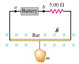
The circuit shown in the figure is used to make a magnetic balance to weigh objects....
The circuit shown in the figure is used to make a magnetic balance
to weigh objects. The mass to
be measured is hung from the center of the bar, that is in a
uniform magnetic field of1.50
to
be measured is hung from the center of the bar, that is in a
uniform magnetic field of1.50 ,directed
into the plane of the figure. The battery voltage can be adjusted
to vary the current in the circuit. The horizontal bar
is60.0
,directed
into the plane of the figure. The battery voltage can be adjusted
to vary the current in the circuit. The horizontal bar
is60.0 long
and is made of extremely light-weight material. It is connected to
the battery by thin vertical wires that can support no appreciable
tension; all the weight of the suspended massis
supported by the magnetic force on the bar. A resistor
with
long
and is made of extremely light-weight material. It is connected to
the battery by thin vertical wires that can support no appreciable
tension; all the weight of the suspended massis
supported by the magnetic force on the bar. A resistor
with =
5.00
=
5.00 is
in series with the bar; the resistance of the rest of the circuit
is much less than this.
is
in series with the bar; the resistance of the rest of the circuit
is much less than this.
 ,what is the greatest massthat this instrument can measure?
Homework Answers
The main concept required to solve this question is force experienced by a rod placed in magnetic field.
To identify the polarity of the two terminals of the battery, initially find the direction of the current in the wire. The direction of current is given by the direction of magnetic force experienced by charged particle.
For the mass of the instrument, first find the current flowing in the circuit by using Ohm’s law. Then use the expression of magnetic force experience by a current carrying
conductor placed in magnetic field.
Equate this force with the weight of the body and solve for the mass of the instrument.
Consider a current carrying conducting rod placed in magnetic field B.
The magnetic force experienced by a rod placed in magnetic field is given by the following formula:
Here, is the angle between the current element in the direction of the current flowing in the loop and magnetic field, l is the length of the rod and I is the current flowing through it.
Let a potential difference of V applied across the rod and R be the resistance in the circuit.
The current flowing through the rod is given as,
The weight  of a mass m is given by following expression:
Here, g is the acceleration due to gravity.
(A)
The direction of the magnetic force experienced by charged rod is given by the following expression:
The weight of the instrument acts vertically downward. So, to hold the mass, the direction of magnetic force should be vertically upwards.
Since, the direction of magnetic field is inwards hence, the direction of must be from left to right to make the fore in the upward direction (The resultant vector of cross product of two vectors always points in the perpendicular direction. The direction can be finding out by the following method:
If first figure of right hand will show the direction of the current and the middle figure will show the direction of the magnetic field then the thumb will show the direction of force.). Hence, the direction of current is anticlockwise.
Since current flows from positive to negative terminal hence, the terminal a will be positive and terminal b will be negative.
(B)
Consider a current carrying conducting rod placed in magnetic field B.
The magnetic force experienced by the rod is,
…… (1)
The current flowing through the rod is given as,
Substitute for I in equation (1).
…… (2)
The weight of a mass m is given by following expression:
Since weight will be balanced by the force given in equation (2) hence, substitute mg for F in equation (2).
Rearrange the above equation for m.
Substitute for V, for g , for R , for B , for and for l.
Ans: Part A
The point a is the positive terminal of the battery.
Part BThe greatest mass that the instrument can measure is .
Add Answer to:
The circuit shown in the figure is used to make a magnetic balance
to weigh objects....
Most questions answered within 3 hours.
-
Hello, can someone please help me answer this question?
How much heat is absorbed by a...
asked 11 minutes ago -
A business executive has the option to invest money in two
plans: Plan A guarantees that...
asked 13 minutes ago -
. A marketing researcher conducted a survey of 25 shoppers
randomly selected at the local mall...
asked 28 minutes ago -
Create an comprehensive response to the
following:
Antimicrobial agents work on a multitude of microbes (bacteria,...
asked 30 minutes ago -
6.13 LAB: Step counter. Section 6.3.
A pedometer treats walking 2,000 steps as walking 1 mile....
asked 25 minutes ago -
(14.2) A block of mass m = 10 kg riding on a frictionless
horizontal plane is...
asked 28 minutes ago -
Use any search engine to search for articles about Starbucks
partnership with Tata Companies in India...
asked 27 minutes ago -
Let’s say that for some reason Bank Excess Reserves suddenly
increase sharply. What effect would this...
asked 36 minutes ago -
Given:
Curent Assets: $600,000
Total Assets: $2,600,000
Current Liabilities: $500,000
Total Liabilities: $1,700,000
What is the...
asked 41 minutes ago -
1. What is a “Bankster”? What is insider trading? Why is it
illegal?
2. What is...
asked 39 minutes ago -
A transverse wave on a cord is given by
D(x,t)=0.18sin(2.7x−61.0t), where Dand x are in m...
asked 46 minutes ago -
ASSIGNMENT
ANSWER ANY TWO OF THE FOLLOWING IN 2-3 PARAGRAPHS OF EACH
QUESTION.
1: Where is...
asked 44 minutes ago