Please use Lagrange's Equation and solve both parts.
Homework Answers


Add Answer to:
Please use Lagrange's Equation and solve both parts.
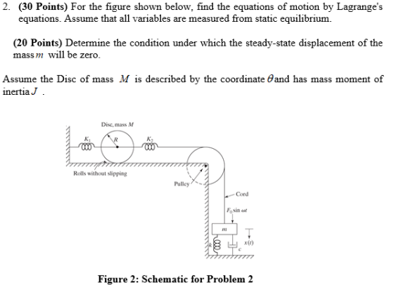
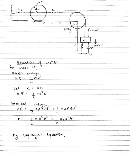
2. (30 Points) For the figure shown below,...
In the pulley system shown in Figure P2.33, assume that the cable is massless and inextensible, and assume that the pu...
 In the pulley system shown in Figure P2.33, assume that the cable is massless and inextensible, and assume that the pulley masses are negligible. The force f is a known function of time. Derive the system's equation of motion in terms of the displacement. For the system shown in Figure P2.34, the solid cylinder of inertia I and mass m rolls without slipping. Neglect the pulley mass and obtain the equation of motion in terms of x.
Solve a,b and c The vibratory movement of the engineering system shown in Figure 3 can...
 Solve a,b and c
The vibratory movement of the engineering system shown in Figure 3 can be described by two generalised coordinates, x, a Cartesian coordinate, and 6, a polar coordinate systems. The mass m and its mass moment of inertia about an axis that goes through its centre of gravity G is J. When the system is slightly pushed down from the top comer at the right hand edge of mass m, the induced vibrational motion is found to...
Solve a,b and c
The vibratory movement of the engineering system shown in Figure 3 can be described by two generalised coordinates, x, a Cartesian coordinate, and 6, a polar coordinate systems. The mass m and its mass moment of inertia about an axis that goes through its centre of gravity G is J. When the system is slightly pushed down from the top comer at the right hand edge of mass m, the induced vibrational motion is found to...
solve with newton's method Q1: Use the equivalent system method to derive the differential equation governing...
 solve with newton's method
Q1: Use the equivalent system method to derive the differential equation governing the free vibrations of the system of Figure below. Use x, the displacement of the mass center of the disk from the system's equilibrium position, as the generalized coordinate. The disk rolls without slipping, no slip occurs at the pulley, and the pulley is frictionless. Include an approximation for the inertia effects of the springs. Each spring has a mass ms. Use newton's method....
solve with newton's method
Q1: Use the equivalent system method to derive the differential equation governing the free vibrations of the system of Figure below. Use x, the displacement of the mass center of the disk from the system's equilibrium position, as the generalized coordinate. The disk rolls without slipping, no slip occurs at the pulley, and the pulley is frictionless. Include an approximation for the inertia effects of the springs. Each spring has a mass ms. Use newton's method....
Please answer that question ASAP 1. Consider a disc and hoop both of the same mass...
 Please answer that question ASAP
1. Consider a disc and hoop both of the same mass M, radius R and thickness I. a) Explain why one of these objects has a larger moment of inertia (about an axis through the center of mass and perpendicular to the plane of the object) than the other. What effect does the thickness I have on the rotational inertia? b) Explain how the rotational inertia of the disc may be obtained by adding the...
Please answer that question ASAP
1. Consider a disc and hoop both of the same mass M, radius R and thickness I. a) Explain why one of these objects has a larger moment of inertia (about an axis through the center of mass and perpendicular to the plane of the object) than the other. What effect does the thickness I have on the rotational inertia? b) Explain how the rotational inertia of the disc may be obtained by adding the...
PROBLEM 3: (40 points) A rigid massless lever ACB, as shown in Figure 3, is pivoting...
 PROBLEM 3: (40 points) A rigid massless lever ACB, as shown in Figure 3, is pivoting about point C. A mass mis attached at point A. Assume frictionless pivot point, frictionless pulley, massless pulley, and small angles. The parameters are Ki-30N/m, m=1 kg, K2-40N/m, C-4.35N-s/m, L=0.4 m, a=0.2 m, and b=0.15 m. (i) Draw the Free Body Diagram (FBD) (5 points). (ii) Use Newton's approach to derive the equations of the motion (10 points). (iii) Use Lagrange's method to derive...
For the apparatus shown in the figure, there is no slipping between the cord and the...
 For the apparatus shown in the figure, there is no slipping between the cord and the surface of the pulley. The blocks have mass of 3.0 kg and 5.7 kg, and the pulley has a radius of R and a mass of 15.4 kg. The moment of inertia of the pulley is EMR. What is the acceleration of the 5.7 kg mass? (Enter your answer in units of m/s2. Only enter the number using 2 significant figures.)
All questions added because it is needed for Question 6 to 11 to be answered (I believe). Answer Question 6 to 11. Ple...
 All questions added because it is needed for Question 6 to 11 to
be answered (I believe).
Answer Question 6 to 11. Please. Thank you
Practical 3: Rotation due to an External Moment - Pre-Lab Preparation Rotation due to an External Moment: Pre-lab Preparation In this practical exercise you will investigate the angular acceleration of a disc about its centre of mass due to an applied moment, and determine the moment of inertia of the disc. Write down the equation...
All questions added because it is needed for Question 6 to 11 to
be answered (I believe).
Answer Question 6 to 11. Please. Thank you
Practical 3: Rotation due to an External Moment - Pre-Lab Preparation Rotation due to an External Moment: Pre-lab Preparation In this practical exercise you will investigate the angular acceleration of a disc about its centre of mass due to an applied moment, and determine the moment of inertia of the disc. Write down the equation...
In the figure below, block 1 has mass m_1 = 460 g, block 2 has mass...
 In the figure below, block 1 has mass m_1 = 460 g, block 2 has mass m_2 = 500 g, and the pulley, which is measured on a horizontal with 2.5200 s without the cord slipping on the pulley. (Do not treat the pulley as a uniform disk Give your answers to three significant figures. Use these rounded values in subsequent calculations) What is the magnitude of the acceleration of the blocks? What is the tension T_2? What is the...
1 Q2. Figure 2 shows a system in which mass m is connected with a cylinder of mass m2 and moment of inertia Jo through...
 1 Q2. Figure 2 shows a system in which mass m is connected with a cylinder of mass m2 and moment of inertia Jo through a horizontal spring k. The cylinder is m1 rolling on the rough surface without slipping. (1) Find its total kinetic energy, total potential energy TN and Lagrangian, Figure 2 (2) Derive the equations of motion using Lagrangian equation method, and (3) Calculate its natural frequencies
1 Q2. Figure 2 shows a system in which mass...
1 Q2. Figure 2 shows a system in which mass m is connected with a cylinder of mass m2 and moment of inertia Jo through a horizontal spring k. The cylinder is m1 rolling on the rough surface without slipping. (1) Find its total kinetic energy, total potential energy TN and Lagrangian, Figure 2 (2) Derive the equations of motion using Lagrangian equation method, and (3) Calculate its natural frequencies
1 Q2. Figure 2 shows a system in which mass...
Problem 2: (30 points) A mode ontrolled DC motor is she l or is shown below....
 Problem 2: (30 points) A mode ontrolled DC motor is she l or is shown below. The em 2: (30 points) A model of an armature contro aller, here modeled as a rigid body with mass load attached to the rotor of the motor is a prope is transmitted to the propeller through a shaft moment of inertia IL. The rotation of the rotor with torsional damping constant br. The proper eller motion generate a further load TL due to...
 In the pulley system shown in Figure P2.33, assume that the cable is massless and inextensible, and assume that the pulley masses are negligible. The force f is a known function of time. Derive the system's equation of motion in terms of the displacement. For the system shown in Figure P2.34, the solid cylinder of inertia I and mass m rolls without slipping. Neglect the pulley mass and obtain the equation of motion in terms of x.
 Solve a,b and c
The vibratory movement of the engineering system shown in Figure 3 can be described by two generalised coordinates, x, a Cartesian coordinate, and 6, a polar coordinate systems. The mass m and its mass moment of inertia about an axis that goes through its centre of gravity G is J. When the system is slightly pushed down from the top comer at the right hand edge of mass m, the induced vibrational motion is found to...
Solve a,b and c
The vibratory movement of the engineering system shown in Figure 3 can be described by two generalised coordinates, x, a Cartesian coordinate, and 6, a polar coordinate systems. The mass m and its mass moment of inertia about an axis that goes through its centre of gravity G is J. When the system is slightly pushed down from the top comer at the right hand edge of mass m, the induced vibrational motion is found to...
 solve with newton's method
Q1: Use the equivalent system method to derive the differential equation governing the free vibrations of the system of Figure below. Use x, the displacement of the mass center of the disk from the system's equilibrium position, as the generalized coordinate. The disk rolls without slipping, no slip occurs at the pulley, and the pulley is frictionless. Include an approximation for the inertia effects of the springs. Each spring has a mass ms. Use newton's method....
solve with newton's method
Q1: Use the equivalent system method to derive the differential equation governing the free vibrations of the system of Figure below. Use x, the displacement of the mass center of the disk from the system's equilibrium position, as the generalized coordinate. The disk rolls without slipping, no slip occurs at the pulley, and the pulley is frictionless. Include an approximation for the inertia effects of the springs. Each spring has a mass ms. Use newton's method....
 Please answer that question ASAP
1. Consider a disc and hoop both of the same mass M, radius R and thickness I. a) Explain why one of these objects has a larger moment of inertia (about an axis through the center of mass and perpendicular to the plane of the object) than the other. What effect does the thickness I have on the rotational inertia? b) Explain how the rotational inertia of the disc may be obtained by adding the...
Please answer that question ASAP
1. Consider a disc and hoop both of the same mass M, radius R and thickness I. a) Explain why one of these objects has a larger moment of inertia (about an axis through the center of mass and perpendicular to the plane of the object) than the other. What effect does the thickness I have on the rotational inertia? b) Explain how the rotational inertia of the disc may be obtained by adding the...
 PROBLEM 3: (40 points) A rigid massless lever ACB, as shown in Figure 3, is pivoting about point C. A mass mis attached at point A. Assume frictionless pivot point, frictionless pulley, massless pulley, and small angles. The parameters are Ki-30N/m, m=1 kg, K2-40N/m, C-4.35N-s/m, L=0.4 m, a=0.2 m, and b=0.15 m. (i) Draw the Free Body Diagram (FBD) (5 points). (ii) Use Newton's approach to derive the equations of the motion (10 points). (iii) Use Lagrange's method to derive...
 For the apparatus shown in the figure, there is no slipping between the cord and the surface of the pulley. The blocks have mass of 3.0 kg and 5.7 kg, and the pulley has a radius of R and a mass of 15.4 kg. The moment of inertia of the pulley is EMR. What is the acceleration of the 5.7 kg mass? (Enter your answer in units of m/s2. Only enter the number using 2 significant figures.)
 All questions added because it is needed for Question 6 to 11 to
be answered (I believe).
Answer Question 6 to 11. Please. Thank you
Practical 3: Rotation due to an External Moment - Pre-Lab Preparation Rotation due to an External Moment: Pre-lab Preparation In this practical exercise you will investigate the angular acceleration of a disc about its centre of mass due to an applied moment, and determine the moment of inertia of the disc. Write down the equation...
All questions added because it is needed for Question 6 to 11 to
be answered (I believe).
Answer Question 6 to 11. Please. Thank you
Practical 3: Rotation due to an External Moment - Pre-Lab Preparation Rotation due to an External Moment: Pre-lab Preparation In this practical exercise you will investigate the angular acceleration of a disc about its centre of mass due to an applied moment, and determine the moment of inertia of the disc. Write down the equation...
 In the figure below, block 1 has mass m_1 = 460 g, block 2 has mass m_2 = 500 g, and the pulley, which is measured on a horizontal with 2.5200 s without the cord slipping on the pulley. (Do not treat the pulley as a uniform disk Give your answers to three significant figures. Use these rounded values in subsequent calculations) What is the magnitude of the acceleration of the blocks? What is the tension T_2? What is the...
 1 Q2. Figure 2 shows a system in which mass m is connected with a cylinder of mass m2 and moment of inertia Jo through a horizontal spring k. The cylinder is m1 rolling on the rough surface without slipping. (1) Find its total kinetic energy, total potential energy TN and Lagrangian, Figure 2 (2) Derive the equations of motion using Lagrangian equation method, and (3) Calculate its natural frequencies
1 Q2. Figure 2 shows a system in which mass...
1 Q2. Figure 2 shows a system in which mass m is connected with a cylinder of mass m2 and moment of inertia Jo through a horizontal spring k. The cylinder is m1 rolling on the rough surface without slipping. (1) Find its total kinetic energy, total potential energy TN and Lagrangian, Figure 2 (2) Derive the equations of motion using Lagrangian equation method, and (3) Calculate its natural frequencies
1 Q2. Figure 2 shows a system in which mass...
 Problem 2: (30 points) A mode ontrolled DC motor is she l or is shown below. The em 2: (30 points) A model of an armature contro aller, here modeled as a rigid body with mass load attached to the rotor of the motor is a prope is transmitted to the propeller through a shaft moment of inertia IL. The rotation of the rotor with torsional damping constant br. The proper eller motion generate a further load TL due to...
Most questions answered within 3 hours.
-
John needs 40 Eternal Light flashlights. Each Eternal Light
flashlight requires 3 bulbs, and each bulb...
asked 1 minute ago -
1) If Nominal GDP is $16,000 billion and the GDP deflator is 50,
then Real GDP...
asked 7 minutes ago -
D. A student completed 20 courses in the School of Arts and
Sciences. Her grades in...
asked 1 hour ago -
teo
pucks moving on a frictionless air table are about to collide. the
1.5 kg puck...
asked 1 hour ago -
Problem #1
The area between Z = 0 and Z = 2.50
The area between Z...
asked 3 hours ago -
1. What is the meaning of the term communication style?
2. What are the benefits to...
asked 2 hours ago -
9.) You are buying a car that cost $26,500. You make payments of
$412 each month...
asked 3 hours ago -
. Suppose a discrete random variable has probability
distribution
P(x) = .2 if x = 0...
asked 4 hours ago -
Under the influence of its drive force, a snowmobile is moving
at a constant velocity along...
asked 5 hours ago -
Why do organizations decline? What steps can top
management take to halt, decline, and restore organizational...
asked 4 hours ago -
What mechanisms Drive speciation??
(I.e. what was Dawins theory on the orgin of species, and how...
asked 6 hours ago -
The manager at a car assembly plant believes that the mean
assembly time for a car...
asked 7 hours ago