Solve the circuit (2)


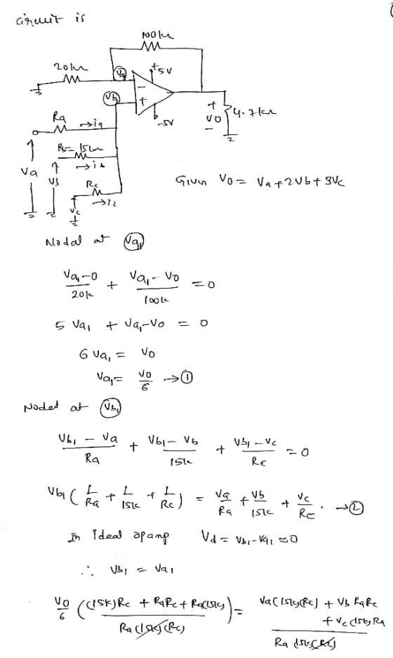
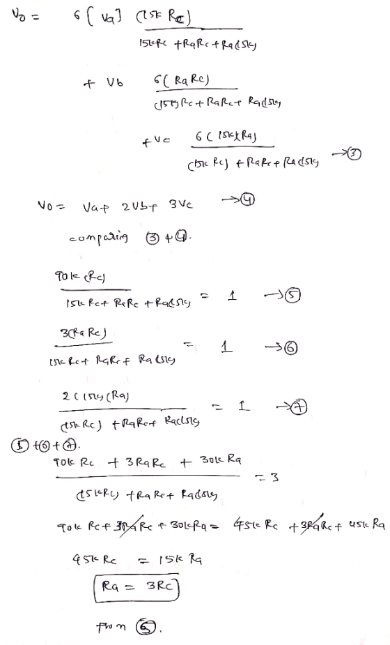
The circuit in (Figure 1) is a non-inverting summing amplifier. Assume the op amp is ideal. Design the circuit so that vo = va + 2ub + 3vc. Part A Specify the numerical value of RA Express your answer to three significant figures and include the appropriate units. Figure < 1 of 1 > View Available Hint(s) 100 k 20 12 S.5V R = Value Units v 34.7k Submit Part B Specify the numerical value of Rc. Express your answer to three significant figures and include the appropriate units. Part B Specify the numerical value of Rc. Express your answer to three significant figures and include the appropriate units. ► View Available Hint(s) ? TE PÅ Value R o E Units Rc = Submit Part C Calculate ia in microamperes when va = 0.6 V, vp = 0.5 V, and Vc = 1 V. Express your answer in microamperes to three significant figures. ► View Available Hint(s) V AC 11 vec R o 2 ? UA la = Submit Part D Calculate ip in microamperes when va = 0.6 V, Ub = 0.5 V, and ve = 1 V. Express your answer in microamperes to three significant figures. ► View Available Hint(s) IVO AQ 11 vec pe o 2 ? HA Submit Part E Calculate ic in microamperes when va = 0.6 V, vb = 0.5 V, and Vc = 1 V. Express your answer in microamperes to three significant figures. ► View Available Hint(s) IVO ALO 11 vec R o 2 ? 2 = μΑ Submit
Homework Answers

The sinusoidal voltage source in the circuit shown in Figure 1) is generating the voltage ,...
 The sinusoidal voltage source in the circuit shown in Figure 1) is generating the voltage , 4cos 2000 V. The op amp is ideal Write the steady-state expression for v.() as vo(t) =V, cos(wt + ), where -180 < < 180° Suppose that R = 45 k2 Express your answer to three significant figures and include the appropriate units. ► View Available Hint(s) "! A V. - 0.812 RO? V Submit Previous Answers * Incorrect; Try Again; 9 attempts remaining...
Part A The current and voltage at the terminals of the inductor in the circuit are...
 Part A The current and voltage at the terminals of the inductor in the circuit are i(t)=(3.4+3.8e-40t)A,t20; v(t)=-63e-40tV,t20+.(Figure 1) Specify the numerical value of V: - Express your answer to three significant figures and include the appropriate units. НА, ? V = Value Units Submit Request Answer Part B Specify the numerical value of R. Express your answer to three significant figures and include the appropriate units. HA ? R= Value Units Submit Request Answer Figure < 1 of 1...
Learning Goal: To analyze and design a passive, first-order low-pass filter using a series RL circuit....
 Learning Goal: To analyze and design a passive, first-order low-pass filter using a series RL circuit. The analysis and design will be repeated for a series RC circuit. An electrocardiogram needs to detect periodic signals of approximately 1 Hz (since the resting heart rate of a healthy adult is between 55 and 70 beats per minute). The instrument operates in an electrical environment that is very noisy with a frequency of 60 Hz. It is desirable to have a low-pass...
Problem 17 Find the g parameters for the circuit in (Figure 1). Take R1 = 212,...
 Problem 17 Find the g parameters for the circuit in (Figure 1). Take R1 = 212, R2 = 202, R3 = 80 2. R4 = 202, and Rs = 60 . art A Find gi1 Express your answer to three significant figures and include the appropriate units. ► View Available Hint(s) LA ? 911 Value Units Submit Figure Part B 1 of 1 Find 921 Express your answer using three significant figures. View Available Hint(s) R R 12 IVO AE...
The current and voltage at the terminals of the inductor in the circuit are i(t) =...
 The current and voltage at the terminals of the inductor in the circuit are i(t) = (4.2 +5e 401) A, t > 0; v (t) = -73e_404 V, t > 0+ (Figure 1) Part A Specify the numerical value of Vs Express your answer to three significant figures and include the appropriate units. HA ? Vs = Value Units Submit Request Answer Part B Specify the numerical value of Express your answer to three significant figures and include the appropriate...
Part A The current and voltage at the terminals of the inductor in the circuit are...
 Part A The current and voltage at the terminals of the inductor in the circuit are i(t) = (3.2+ 3e 401) A, t > 0; v(t) = –80e-40+ V, t > 0+.(Figure 1) Specify the numerical value of V. Express your answer to three significant figures and include the appropriate units. НА ? Value Units Submit Request Answer Part B Figure 1 of 1 Specify the numerical value of R. Express your answer to three significant figures and include the...
The current and voltage at the terminals of the inductor in the circuit are i(t) =...
 The current and voltage at the terminals of the inductor in the circuit are i(t) = (3.7+3.8e-406) A, t > 0; v(t) = -82e-40 V, t > 0+ (Figure 1) Part A Specify the numerical value of Vs. Express your answer to three significant figures and include the appropriate units. НА, ? V = Value Units Submit Request Answer Part B Specify the numerical value of R. Express your answer to three significant figures and include the appropriate units. HA...
Part B - Designing and analyzing a series RC high-pass filter Using the available 3.2 uF...
 Part B - Designing and analyzing a series RC high-pass filter Using the available 3.2 uF capacitor, what is the value of the resistor needed to make a high-pass filter with a cutoff frequency of 2800 Hz? Express your answer to three significant figures and include appropriate units. View Available Hint(s) НА ? R = Value Units Submit Part C - Measuring the effectiveness of the series RC high-pass filter To measure the effectiveness of the design, find the magnitude...
The current and voltage at the terminals of the inductor in the circuit are i (t)...
 The current and voltage at the terminals of the inductor in the circuit are i (t) = (3.8+3.5e -40t) A, t > 0; v (t) = -86e V, t > 07.(Figure 1) -400 Figure < 1 of 1 R + V 46 + t=0 L 3vt) U Part A Specify the numerical value of Vs. Express your answer to three significant figures and include the appropriate units. μΑ ? Vs = Value Units Part B Specify the numerical value of...
Problem 5.4 Review1 Constants The op amp in the circuit in (Figure 1) is ideal. Figure...
 Problem 5.4 Review1 Constants The op amp in the circuit in (Figure 1) is ideal. Figure 1 of 1 100) kΩ 16 V 20 kΩ 40 kΩ -16 V Ub Part A Calculate vo if ua = 4 V and vb = 0 V Express your answer to three significant figures and include the appropriate units. Vo = 1-20 Submit X Incorrect; Try Again Part B Calculate uo if Va-2 V and vb = 0 V Express your answer to...
 The sinusoidal voltage source in the circuit shown in Figure 1) is generating the voltage , 4cos 2000 V. The op amp is ideal Write the steady-state expression for v.() as vo(t) =V, cos(wt + ), where -180 < < 180° Suppose that R = 45 k2 Express your answer to three significant figures and include the appropriate units. ► View Available Hint(s) "! A V. - 0.812 RO? V Submit Previous Answers * Incorrect; Try Again; 9 attempts remaining...
 Part A The current and voltage at the terminals of the inductor in the circuit are i(t)=(3.4+3.8e-40t)A,t20; v(t)=-63e-40tV,t20+.(Figure 1) Specify the numerical value of V: - Express your answer to three significant figures and include the appropriate units. НА, ? V = Value Units Submit Request Answer Part B Specify the numerical value of R. Express your answer to three significant figures and include the appropriate units. HA ? R= Value Units Submit Request Answer Figure < 1 of 1...
 Learning Goal: To analyze and design a passive, first-order low-pass filter using a series RL circuit. The analysis and design will be repeated for a series RC circuit. An electrocardiogram needs to detect periodic signals of approximately 1 Hz (since the resting heart rate of a healthy adult is between 55 and 70 beats per minute). The instrument operates in an electrical environment that is very noisy with a frequency of 60 Hz. It is desirable to have a low-pass...
 Problem 17 Find the g parameters for the circuit in (Figure 1). Take R1 = 212, R2 = 202, R3 = 80 2. R4 = 202, and Rs = 60 . art A Find gi1 Express your answer to three significant figures and include the appropriate units. ► View Available Hint(s) LA ? 911 Value Units Submit Figure Part B 1 of 1 Find 921 Express your answer using three significant figures. View Available Hint(s) R R 12 IVO AE...
 The current and voltage at the terminals of the inductor in the circuit are i(t) = (4.2 +5e 401) A, t > 0; v (t) = -73e_404 V, t > 0+ (Figure 1) Part A Specify the numerical value of Vs Express your answer to three significant figures and include the appropriate units. HA ? Vs = Value Units Submit Request Answer Part B Specify the numerical value of Express your answer to three significant figures and include the appropriate...
 Part A The current and voltage at the terminals of the inductor in the circuit are i(t) = (3.2+ 3e 401) A, t > 0; v(t) = –80e-40+ V, t > 0+.(Figure 1) Specify the numerical value of V. Express your answer to three significant figures and include the appropriate units. НА ? Value Units Submit Request Answer Part B Figure 1 of 1 Specify the numerical value of R. Express your answer to three significant figures and include the...
 The current and voltage at the terminals of the inductor in the circuit are i(t) = (3.7+3.8e-406) A, t > 0; v(t) = -82e-40 V, t > 0+ (Figure 1) Part A Specify the numerical value of Vs. Express your answer to three significant figures and include the appropriate units. НА, ? V = Value Units Submit Request Answer Part B Specify the numerical value of R. Express your answer to three significant figures and include the appropriate units. HA...
 Part B - Designing and analyzing a series RC high-pass filter Using the available 3.2 uF capacitor, what is the value of the resistor needed to make a high-pass filter with a cutoff frequency of 2800 Hz? Express your answer to three significant figures and include appropriate units. View Available Hint(s) НА ? R = Value Units Submit Part C - Measuring the effectiveness of the series RC high-pass filter To measure the effectiveness of the design, find the magnitude...
 The current and voltage at the terminals of the inductor in the circuit are i (t) = (3.8+3.5e -40t) A, t > 0; v (t) = -86e V, t > 07.(Figure 1) -400 Figure < 1 of 1 R + V 46 + t=0 L 3vt) U Part A Specify the numerical value of Vs. Express your answer to three significant figures and include the appropriate units. μΑ ? Vs = Value Units Part B Specify the numerical value of...
 Problem 5.4 Review1 Constants The op amp in the circuit in (Figure 1) is ideal. Figure 1 of 1 100) kΩ 16 V 20 kΩ 40 kΩ -16 V Ub Part A Calculate vo if ua = 4 V and vb = 0 V Express your answer to three significant figures and include the appropriate units. Vo = 1-20 Submit X Incorrect; Try Again Part B Calculate uo if Va-2 V and vb = 0 V Express your answer to...
Most questions answered within 3 hours.
-
Please explain steps:
An 80 kg swimmer steps off a platform 10 m above the water...
asked 4 minutes ago -
A lottery exists where balls numbered 1 to 17 are placed in an
urn. To win,...
asked 7 minutes ago -
26) Briefly describe, using words or simple diagrams, the
chemiosmotic theory for coupling oxidation to phosphorylation...
asked 2 hours ago -
Suppose that XX is a random variable with mean 16 and standard
deviation 5 . Also...
asked 2 hours ago -
Calculate the number density of argon gas at a temperature of
24C and a pressure of...
asked 6 hours ago -
Alternative
Classification
How to Estimate
Probabilities from Data? ( For continuous Attributes)
And How to generate...
asked 6 hours ago -
An explosion breaks a 20.0-kg object into three parts. The
object is initially moving at a...
asked 6 hours ago -
Calculate the approximate number of residues of Rubisco, which
is involved in carbon fixation in plants,...
asked 7 hours ago -
Other decisions about scientific claims can have a much broader
impact.ENERGYarrow-10x10.png, environment, health, security - all...
asked 8 hours ago -
I need to write a research paper and work cited about this
topic: The United States...
asked 9 hours ago -
Hello! I was wondering if I could have some help?
If the vapor pressure of carvone...
asked 9 hours ago -
An economist wants to estimate the mean per capita income (in
thousands of dollars) for a...
asked 9 hours ago