


Homework Answers


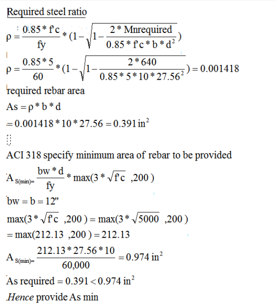


2)
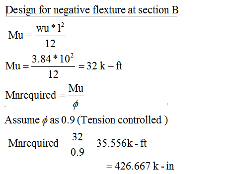
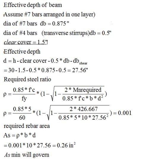
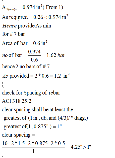


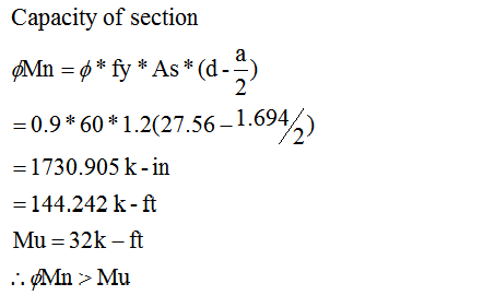
Note
beam is lightly loaded and span is relatively small
so minimum rebar required governed the design for both section
contribution of flange is not taken for both design
Add Answer to:
Based on tributary load analysis, the dead and live loads, wd and wų, respectively, acting on...
Design a rectangular simple supported beam to carry service loads of 1.05 kips/ft of dead load...
Design a rectangular simple supported beam to carry service loads of 1.05 kips/ft of dead load (DL) (self-weight included) and 2.47kip/ft live load (LL) on a span length of 18 ft. The beam is limited to be (due to architectural reasons) 10” wide with an overall depth of 20”. Use f’c= 3,000 psi and fy= 40,000psi. Design the longitudinal reinforcement (flexure design) and the web reinforcement (Stirrups).
Design a rectangular simple supported beam to carry service loads of 1.05 kips/ft of dead load...
 Design a rectangular simple supported beam to carry service loads of 1.05 kips/ft of dead load (DL) (self-weight included) and 2.47kip/ft live load (LL) on a span length of 18 ft. The beam is limited to be (due to architectural reasons) 10” wide with an overall depth of 20”. Use f’c= 3,000 psi and fy=40,000psi. Design the longitudinal reinforcement (flexure design) and the web reinforcement (Stirrups).
Could you please help me on question 7. Thank you very much. The floor system shown...
 Could you please help me on question 7.
Thank you very much.
The floor system shown below consists of normalweight concrete (150 pcf). Beams C2 ! LT 1 7.0 inch ! h=20 in G2! 12 in Girders BI 1 7.0 inch Slab 8 ft span h 24 in ----- - -- - --- 15 in 15 ft 15 ft Use 4000 psi concrete and Gr. 60 reinforcing steel. Assume 0.75 inch clear cover. Include concrete self-weight and a superimposed dead...
Could you please help me on question 7.
Thank you very much.
The floor system shown below consists of normalweight concrete (150 pcf). Beams C2 ! LT 1 7.0 inch ! h=20 in G2! 12 in Girders BI 1 7.0 inch Slab 8 ft span h 24 in ----- - -- - --- 15 in 15 ft 15 ft Use 4000 psi concrete and Gr. 60 reinforcing steel. Assume 0.75 inch clear cover. Include concrete self-weight and a superimposed dead...
UDL BB 300mm 200mm 8m ELEVATION SECTION Live Load: WQ = 2kN/m Uniformly Distributed Dead Load:...
 UDL BB 300mm 200mm 8m ELEVATION SECTION Live Load: WQ = 2kN/m Uniformly Distributed Dead Load: WG = 11.5kN/m Uniformly Distribted Ultimate Design Load: W* = 16.8kN/m 35mm effective cover 32MPa grade concrete Unit Weight of Concrete = 25kN/m2 Ec = 30,000MPa n = 6.6 Design Bending Moment: M* = 134kN/m Short - Term Bending Moment: M*5 = 103kNm Long-Term Bending Moment: M*sus = 98kNm Direct Tensile Stength: f'ct = 2.0MPa Flexural Tensile Stength: f'ct = 3.4MPa Determine the area...
i have also attached the solutions. could you please explain step by step what they are...
 i have also attached the solutions.
could you please explain step by step what they are doing.
especially the bit in part (a) where they do x/d
Question 2 Picture it. It's 5 o'clock on Friday and at the end of a long week all Dave wants to do is go home. But his boss has other ideas; he tells Dave that he can go once he has designed the tension reinforcement for the beam in Figure 2. a) Design...
i have also attached the solutions.
could you please explain step by step what they are doing.
especially the bit in part (a) where they do x/d
Question 2 Picture it. It's 5 o'clock on Friday and at the end of a long week all Dave wants to do is go home. But his boss has other ideas; he tells Dave that he can go once he has designed the tension reinforcement for the beam in Figure 2. a) Design...
 Design a rectangular simple supported beam to carry service loads of 1.05 kips/ft of dead load (DL) (self-weight included) and 2.47kip/ft live load (LL) on a span length of 18 ft. The beam is limited to be (due to architectural reasons) 10” wide with an overall depth of 20”. Use f’c= 3,000 psi and fy=40,000psi. Design the longitudinal reinforcement (flexure design) and the web reinforcement (Stirrups).
 Could you please help me on question 7.
Thank you very much.
The floor system shown below consists of normalweight concrete (150 pcf). Beams C2 ! LT 1 7.0 inch ! h=20 in G2! 12 in Girders BI 1 7.0 inch Slab 8 ft span h 24 in ----- - -- - --- 15 in 15 ft 15 ft Use 4000 psi concrete and Gr. 60 reinforcing steel. Assume 0.75 inch clear cover. Include concrete self-weight and a superimposed dead...
Could you please help me on question 7.
Thank you very much.
The floor system shown below consists of normalweight concrete (150 pcf). Beams C2 ! LT 1 7.0 inch ! h=20 in G2! 12 in Girders BI 1 7.0 inch Slab 8 ft span h 24 in ----- - -- - --- 15 in 15 ft 15 ft Use 4000 psi concrete and Gr. 60 reinforcing steel. Assume 0.75 inch clear cover. Include concrete self-weight and a superimposed dead...
 UDL BB 300mm 200mm 8m ELEVATION SECTION Live Load: WQ = 2kN/m Uniformly Distributed Dead Load: WG = 11.5kN/m Uniformly Distribted Ultimate Design Load: W* = 16.8kN/m 35mm effective cover 32MPa grade concrete Unit Weight of Concrete = 25kN/m2 Ec = 30,000MPa n = 6.6 Design Bending Moment: M* = 134kN/m Short - Term Bending Moment: M*5 = 103kNm Long-Term Bending Moment: M*sus = 98kNm Direct Tensile Stength: f'ct = 2.0MPa Flexural Tensile Stength: f'ct = 3.4MPa Determine the area...
 i have also attached the solutions.
could you please explain step by step what they are doing.
especially the bit in part (a) where they do x/d
Question 2 Picture it. It's 5 o'clock on Friday and at the end of a long week all Dave wants to do is go home. But his boss has other ideas; he tells Dave that he can go once he has designed the tension reinforcement for the beam in Figure 2. a) Design...
i have also attached the solutions.
could you please explain step by step what they are doing.
especially the bit in part (a) where they do x/d
Question 2 Picture it. It's 5 o'clock on Friday and at the end of a long week all Dave wants to do is go home. But his boss has other ideas; he tells Dave that he can go once he has designed the tension reinforcement for the beam in Figure 2. a) Design...
Most questions answered within 3 hours.
-
Write a program to solve the Josephus problem, with the following
modification:
Sample Input:
./a.out n...
asked 1 hour ago -
At the start of a CD it is spinning at a rate of 525 rpm
(revolutions...
asked 2 hours ago -
4. Without doing any calculations, predict whether the observed
∆T would increase, decrease or remain the...
asked 3 hours ago -
Based on the range, which of the following sets of scores has
the greatest variability? 3,...
asked 4 hours ago -
Ripples in a pond travel at a velocity of 3 m/s with one peak
passing a...
asked 4 hours ago -
A man stands on the roof of a building of height 13.0 mm and
throws a...
asked 4 hours ago -
The extent to which assets are financed by borrowed funds and
other liabilities is indicated by:...
asked 5 hours ago -
Explain in detail
Germany is the fifth largest economy
explain what goods and services Germany specializes...
asked 5 hours ago -
The density of platinum is 21.45 g/mL. If a cube of platinum
with a mass of...
asked 6 hours ago -
Accounts Receivable
Sales
A/R Posting
Extended Sales Invoice
Packing Slip
Compare invoice to packing slip 2...
asked 6 hours ago -
Michaella, age 23, is a full-time law student and is claimed by
her parents as a...
asked 6 hours ago -
Why are polymers not typically casted into products?
asked 6 hours ago